3-p0701-0768-cl_en 51 / 69
10秒後にBOOKのページに移動します
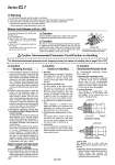
Manual Lock Release (o40 to o100) Bolt Cap Lock-up port Lock-up unit Cylinder During installation adjustment, perform the operation by applying air pressure only to the lock-up port. (On cylinders o125 to o160, the lock cannot be disengaged manually.) o40 to o100 Caution The lock is manually disengaged at the time the cylinder is shipped from the factory. Because the lock will not operate in this state, make sure to change it to the locked state before operation, after having adjusted the axial center for installation. (Only o40 to o100) Caution 1. Do not unlock manually until the safety is confirmed. 2. Perform the unlocking after the residual pressure inside the system has been exhausted. 3. Take measures to prevent the load from dropping when unlocking is performed. . Perform work with the load in its lowest position. . Take measures for drop prevention by strut, etc. Warning Caution Recommended Pneumatic Circuit/Caution on Handling For Selection/recommended pneumatic circuit, stopping accuracy and caution on handling, refer to pages 702 to 705. Caution Caution Caution Stopping Accuracy Caution on Handling Recommended Pneumatic Circuit 1. Load fluctuations during the reciprocal movement of the piston could cause the piston speed to change. A change in the piston speed could greatly increase the variance in the piston’s stopping position. Therefore, take appropriate measures so that the piston speed becomes constant during the piston's reciprocal movement, particularly just before stopping. 2. During a cushioning stroke, or when the piston is in the acceleration region following the start of its travel, there is a large change in speed. Thus, the variance in the stopping position will also be large. Therefore, when effecting a step movement in which the stroke from the start of the operation to the next position is short, be aware of the possibility of being unable to attain the accuracy. 3. Precautions regarding lock-up after the piston has been stopped with an external stopper: To apply the lock-up after the piston has been stopped by an external stopper other than the locked-up mechanism, including stoppage by the stroke end of the cylinder, be aware of the matters described below. Due to the nature of the lock-up mechanism, there is an axial play of about 0.5 to 1.0 mm. Furthermore, due to pipe routing conditions, if it takes longer for the air to discharge through the lock-up port than for the balance pressure to stabilize, causing a delay in locking, the piston rod will move for an amount that is equivalent to the “play + delay”. 4. Immediately before a lock stop, drop the piston speed to 200 mm/s or lower by switching the speed controller (to the bypass circuit). Then, operate the lock-up. Piston speed over 200 mm/s (When locking) 1. Flushing Before piping is connected, it should be thoroughly blown out with air (flushing) or washed to remove cutting chip, cutting oil and other debris from inside the pipe. 2. The load on the piston rod Use the cylinder in the state in which the load to the piston rod is always applied in the axial direction. This must be more strictly adhered to than with ordinary air cylinders. Furthermore, use a guide to control the movement of the load so as not to cause chatter or twist. 3. A rotational force against the piston rod Avoid applying a rotational force against the piston rod. In particular, the application of a rotational force must be prevented when in a lock-up state. 4. Protecting the sliding portion of the rod Use caution that no scratch or dent will be given to the slide part of the guide rod, as this could damage the seals and lead to leaks or faulty lock-up. 5. Lubrication It is not necessary to lubricate the CL series because it is the non-lube style. Never lubricate it because doing so will cause faulty lock-up. For recommended pneumatic circuits, refer to page 704. 1. Operating the pneumatic circuit Instead of the conventional reciprocal air cylinder circuit, use an pneumatic circuit, such as the recommended circuit, in which measures are taken to prevent the piston from lurching after the lock-up has been disengaged. o125 to o160 For cylinders o40 to o100, verify the portion that is stamped on the cap of the lock. 3. Maximum speed and maximum load Never lock up a cylinder that involves a kinetic energy that exceeds the maximum speed or the maximum load indicated in the specifications. Retraction locking 2. Lock-up direction The lock-up is unidirectional. The locking direction is in accordance with the position of the lock-up port, as shown in the figure below. Extension locking Lock-up port To manually disengage the lock, perform the following steps: 1. Open the rubber cap. 2. Apply 0.2 MPa to 0.3 MPa of air pressure to the locking port, and bring the tilted ring upright. 3. Screw a bolt of an appropriate length into the ring tap. The bolt size is M5 for o40 and o50, and M6 for o63, o80, and o100. 750 Series CL1