3-p0701-0768-cl_en 5 / 69
10秒後にBOOKのページに移動します
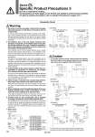
W . The symbol for the fine lock cylinder and lock-up cylinder in the pneumatic circuit uses SMC original symbol. (Fine lock cylinder) Pneumatic Circuit Warning SOL.A SOL.C SOL.B W SOL.B SOL.C SOL.A W SOL.C SOL.B SOL.A ON OFF ON ON ON OFF ON ON SOL.B ON OFF OFF ON OFF OFF OFF OFF SOL.C OFF OFF OFF OFF ON OFF OFF ON Caution W SOL.C SOL.B SOL.A W SOL.B SOL.C SOL.A W SOL.B SOL.A SOL.C 1. Be certain to use an pneumatic circuit which will apply balancing pressure to both sides of the piston when in a locked stop. In order to prevent cylinder lurching after a lock stop, when restarting or when manually unlocking, a circuit should be used to which will apply balancing pressure to both sides of the piston, thereby canceling the force generated by the load in the direction of piston movement. 2. The effective area of the lock release solenoid valve should be at least 50% of the effective area of the cylinder driving solenoid valve, and it should be installed as close to the cylinder as possible so that it is closer than the cylinder driving solenoid valve. If the effective area of the lock release solenoid valve is smaller than the cylinder driving solenoid valve or if it is installed at a distance from the cylinder, the time required for exhausting air for releasing the lock will be longer, which may cause a delay in the locking operation. The delay in the locking operation may result in problems such as increase of overrunning when performing intermediate stop or emergency stop during operation, or if maintaining position from the operation stop state such as drop prevention, workpieces may be dropped depending on the timing of the load action to the operation delay of the lock. 3. Avoid backflow of the exhaust pressure when there is a possibility of interference of exhaust air, for example for a common exhaust type valve manifold. The lock may not operate properly when the exhaust air pressure backflows due to interference of the exhaust air when exhausting air for lock release. It is recommended to use an individual exhaust type manifold or individual valves. 4. Allow at least 0.5 seconds from a locked stop (intermediate stop of the cylinder) until release of the lock. When the locked stop time is too short, the piston rod (and load) may lurch at a speed greater than the control speed of the speed controller. 5. When restarting, control the switching signal for the unlocking solenoid valve so that it acts before or at the same time as the cylinder drive solenoid valve. If the signal is delayed, the piston rod (and load) may lurch at a speed greater than the control speed of the speed controller. 6. Carefully check for dew condensation due to repeated air supply and exhaust of the locking solenoid valve. The operating stroke of the lock part is very small. So, if the piping is long and the air supply and exhaust are repeated, the dew condensation caused by the adiabatic expansion accumulates in the lock part. This may corrode internal parts, causing air leak or lock release fault. 7. Basic circuit 1. A 3 position pressure center solenoid valve and regulator with check valve can be replaced with two 3 port normally open valves and a regulator with relief function. 1) [Horizontal] Forward Backward 3 port normally closed SOL.A Pressure center Regulator with check valve Action Forward Locked stop Unlocked Forward Backward Locked stop Unlocked Backward 0.5 s or more 0 to 0.5 s 0.5 s or more 0 to 0.5 s 2) [Vertical] Load in the direction of rod retraction Load in the direction of rod extension 2) [Vertical] Load in the direction of rod retraction Load in the direction of rod extension [Example] 1) [Horizontal] 3 port normally open 3 port normally closed Regulator with relief function Cylinder side Cylinder side 704 Series CL Specific Product Precautions 3 Be sure to read before handling. The precautions on these pages are for the fine lock cylinders and the lock-up cylinders. For general actuator precautions, refer to Actuator Precautions on pages 3 to 7.