3-p0701-0768-cl_en 68 / 69
10秒後にBOOKのページに移動します
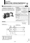
BA BX BY BA Symbol 1 Large Bore Lock-up Cylinder -X50 Series CL1 Made to Order: Individual Specifications 1 Please contact SMC for detailed dimensions, specifications and lead times. CL1 Mounting style Bore size Stroke Locking direction Suffix X50 Specifications o180, o200, o250, o300 0.97 MPa 200 mm/sec 180 12250 6125 24500 200 14700 7350 29400 250 24000 12000 48000 300 29400 14700 58800 180 200 250 300 BA 18.5 18.5 23 23 BP 3 4 3 4 1 1 BX 142 149 184 220 BY 180 191 235 280 X 461 472 577.5 652.5 mm This is a lock-up cylinder with a self-locking system that can be mounted onto a large bore air cylinder (Series CS1) from o180 to o300, and contains a ring that is tilted by a spring force, which is further tilted by the thrust of the cylinder to securely lock the piston rod. Dimensions Applicable bore size Maximum operating pressure Locked-up releasing pressure Locked-up starting pressure Locked-up direction Mounting Maximum speed at locked-up 0.2 MPa or more (at no-load) 0.05 MPa or less One way (Locking direction is selectable.) Basic style, Foot style, Rod side flange style Head side flange style, Single cle vis style Double clevis style, Center trunnion style Maximum Load and Holding Force of Locking (Max. static load) Bore size (mm) Holding force (N) Max. load according to mounting orientation (N) Horizontal mounting Vertical mounting . The cylinder can be used to 1/2 of its holding force or below if only a stationary load is applied, such as for drop prevention. Note) Produced upon receipt of order. For details, contact SMC. Unlocked when pressurized (A) Rc BP lock-up port Unlocked when pressurized (B) Rc BP lock-up port Position of locked-up port (A) Lock at forward (B) Lock at backward X + Stroke Bore size (mm) . For dimensions according to mounting style, refer to Series CS1. . Added the length of BY for full length dimension. 767 CLJ2 CLM2 CLG1 CL1 MLGC CNG MNB CNA2 CNS CLS CLQ RLQ MLU MLGP ML1C D- -X