3-p0701-0768-cl_en 69 / 69
10秒後にBOOKのページに移動します
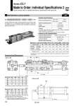
BU BW BX BP BU BX BY BY Symbol 2 Both-direction Lock-up Cylinder -X51 Series CL1 Made to Order: Individual Specifications 2 Please contact SMC for detailed dimensions, specifications and lead times. X + Stroke X + Stroke 40 50 63 80 100 BU 48 56 62 66 74 BW 31 30 30 34 34 BX 59 67 73 77 85 BY 137 153 165 181 197 X 283 312 335 385 412 125 140 160 BU 95.5 104.5 112.5 BP 3/8 3/8 3/8 BX 191 209 225 BY 220 238 259 X 455 473 515.5 Construction/Dimensions CL1 Mounting style Bore size Stroke Suffix X51 Cylinder Specifications Locked-up Unit Specifications 0.08 MPa 50 to 200 mm/s 588 294 1230 981 490 1920 1470 735 3060 2450 1230 4930 3820 1910 7700 6010 3000 12100 7540 3770 15100 9850 4920 19700 o40 to o100 o125 to o160 1.0 MPa 0.97 MPa 40 50 63 80 100 125 140 160 o40 to o100 o125 to o160 . A maximum speed of 500 mm/s is possible if the piston is locked in the stationary state for the purpose of drop prevention. Make sure that the piston speed does not exceed 200 mm/s during locking. . The cylinder can be used to 1/2 of its holding force or below if only a stationary load is applied, such as for drop prevention. A style of Series CA1 (o40 to o100) and Series CS1 (o125 to o160) air cylinder, this is a bi-directional locked-up cylinder in which two uni-directional locked-up units have been assembled by facing them away from each other. Maximum operating pressure Minimum operating pressure Action Piston speed . Cushion Double acting Equipped Locked-up releasing pressure Locked-up starting pressure Locked-up direction Maximum speed at locked-up 0.2 MPa or more (at no-load) 0.05 MPa or less Both directions 200 mm/s Maximum Load and Holding Force of Locking (Max. static load) Bore size (mm) Holding force (N) Max. load according to mounting orientation (N) Horizontal mounting Vertical mounting Bore size (mm) Bore size (mm) . For dimensions according to mounting style, refer to Series CL1. . For dimensions according to mounting style. refer to Series CS1. . Added the length of BY for full length dimension. Note) Locked-up port: o40 to o100 . 2 positions, o125 to o160 . 1 position. In the case of lock releasing of o40 to o100, be sure to supply air to both locked-up ports and to release the lock. (mm) (mm) 768