3-p0701-0768-cl_en 9 / 69
10秒後にBOOKのページに移動します
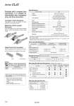
Head Cover Port Location Either perpendicular to the cylinder axis or in-line with the cylinder axis is available for basic style. Axial Perpendicular Specifications Bore size (mm) Action Lubricant Lock operation Fluid Proof pressure Maximum operating pressure Minimum operating pressure Ambient and fluid temperature Piston speed Cushion Stroke length tolerance Mounting 16 Double acting, Single rod Not required (Non-lube) Spring locking (Exhaust locking) Pneumatic locking (Pressure locking) Spring and pneumatic locking Air 1.05 MPa 0.7 MPa 0.08 MPa 50 to 500 mm/s . Rubber bumper Basic style, Axial foot style, Rod side flange style, Double clevis style Without auto switch: .10 to 70 C (No freezing) With auto switch: .10 to 60 C (No freezing) + 1.0 0 Fine Lock Specifications Fluid Maximum operating pressure Unlocking pressure Lock starting pressure Locking direction Lock operation Spring locking (Exhaust locking) Spring and pneumatic locking Pneumatic locking (Pressure locking) Air 0.5 MPa Both directions 0.3 MPa or more 0.25 MPa or less 0.1 MPa or more 0.05 MPa or more Standard Stroke/ (mm) Bore size (mm) 16 Standard stroke 15, 30, 45, 60, 75, 100, 125, 150, 175, 200 Mounting Bracket and Accessory/For details, refer to page 713. Mounting Standard equipment Option Mounting nut Rod end nut Clevis pin Single knuckle joint Double knuckle joint (With pin) T-bracket Basic style Axial foot style Rod side flange style Double clevis style Mounting Bracket Part No. Mounting bracket Foot Flange T-bracket . Part no. CLJ-L016B CLJ-F016B CJ-T016B . T-bracket is used with double clevis (D). -XA Change of rod end shape Symbol Specifications . Pins and retaining rings are packaged together with double clevis and double knuckle joint. . Manufacture of intermediate strokes at 1 mm intervals is possible. (Spacers are not used.) Refer to the minimum auto switch mounting stroke (page 715) for those with an auto switch. Refer to pages 714 to 716 for cylinders with auto switches. ・ Minimum auto switch mounting stroke ・ Proper auto switch mounting position (detection at stroke end) and mounting height ・ Operating range ・ Switch mounting bracket: Part no. Provided with a compact lock mechanism, it is suitable for intermediate stop, emergency stop, and drop prevention. Locking in both directions The piston rod can be locked in either direction of its cylinder stroke. Maximum piston speed: 500 mm/s It can be used at 50 to 500 mm/s provided that it is within the allowable kinetic energy range. . Constraints associated with the allowable kinetic energy are imposed on the speeds at which the piston can be locked. The maximum speed of 750 mm/s can be accommodated if the piston is to be locked in the stationary state for the purpose of drop prevention. . Series CLJ2 Made to Order Specifications (For details, refer to pages 2009 to 2152.) 708