3-p0977-0994-mlu_en 10 / 19
10秒後にBOOKのページに移動します
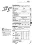
-XC87 Heavy duty (o40 and o50 only) Symbol Specifications Standard Stroke Size 25, 32, 40, 50 Max. manufacturable stroke 300 Standard stroke (mm) 5, 10, 15, 20, 25, 30, 35, 40, 45, 50 75, 100, 125, 150, 175, 200, 250, 300 Cylinder Specifications Non-rotating Rod Accuracy Size Double acting, Single rod Air 1.05 MPa 0.7 MPa 0.2 MPa Note) 屰10 to 60屟C (with no freezing) Not required (Non-lube) Rubber bumper (Standard) 50 to 500 mm/s 1/8 25 32 40 50 M5 x 0.8 1/4 Size Non-rotating rod accuracy 25 ±1° 32 ±0.8° 40 50 ±0.5° Lock Specifications Size Locking action Unlocking pressure Locking pressure Locking direction Maximum operating pressure Unlocking port connection size (Rc, NPT, G) Holding force N (maximum static load) Note) Spring locking (Exhaust locking) 0.2 MPa or more 0.05 MPa or less One direction (Either extension locking or retraction locking) 0.7 MPa 25 32 40 50 245 403 629 982 M5 x 0.8 1/8 Note) The minimum operating pressure of the cylinder is 0.1 MPa when the cylinder and lock are connected to separate ports. Note) The holding force (max. static load) shows the maximum capability and does not show the normal holding capability. So, select an appropriate cylinder while referring to page 980. . Strokes other than listed above will be produced upon request of order. Please consult with SMC. .. Strokes longer than 300 mm are not available. Weight Basic weight Attached metal weight Basic style Axial foot style Flange style: Rod/Head Single clevis style Double clevis style (with pin) Single clevis style (Double clevis bracket) Double clevis style (Single clevis bracket) Single knuckle joint Double knuckle joint (with pin) Additional weight per each 50 mm of stroke Unit: kg 25 0.34 0.41 0.44 0.40 0.41 0.12 0.06 0.07 0.03 0.05 32 0.58 0.72 0.72 0.70 0.74 0.16 0.12 0.16 0.04 0.09 40 0.87 1.08 1.10 1.09 1.13 0.22 0.22 0.26 0.07 0.14 50 1.52 1.86 1.98 1.92 1.99 0.34 0.40 0.47 0.16 0.29 Note) The weight of the attached metal single clevis and double clevis include the weight of two pieces of mounting bolts. Calculation method.Example: MDLUL32-100D-F 傒 Basic weight・ ・ ・ ・ ・ ・ ・ ・ ・ ・ ・ ・ ・ ・ ・ ・ ・ ・ ・ ・ 0.72 (axial foot type ・ size 32) 傒 Additional weight・ ・ ・ ・ ・ ・ ・ ・ ・ ・ ・ ・ ・ ・ ・ ・ 0.16/50 stroke 傒 Stroke ・ ・ ・ ・ ・ ・ ・ ・ ・ ・ ・ ・ ・ ・ ・ ・ ・ ・ ・ ・ ・ ・ ・ ・ ・ 100 stroke 0.72 +100/50 x 0.16 = 1.04 kg Refer to pages 992 to 994 for cylinders with Size auto switches. . Minimum auto switch mounting stroke . Proper auto switch mounting position (detection at stroke end) and mounting height . Operating range . Switch mounting bracket: Part no. Action Fluid Proof pressure Maximum operating pressure Minimum operating pressure Ambient and fluid temperature Lubrication Cushion Stroke length tolerance Piston speed Cylinder port size (Rc, NPT, G) +1.4 0 Plate Cylinder with Lock Series MLU Made to Order (For details, refer to pages 2033 to 2152.) 985 CLJ2 CLM2 CLG1 CL1 MLGC CNG MNB CNA2 CNS CLS CLQ RLQ MLU MLGP ML1C D-𡱖 -X𡱖