3-p0977-0994-mlu_en 5 / 19
10秒後にBOOKのページに移動します
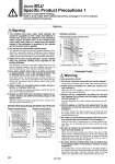
o40 o50 o25 o32 o40 o50 o25 o32 1 10 100 1 10 100 100 500 Maximum speed mm/s Load mass kg 100 500 Maximum speed mm/s Load mass kg Selection Warning 1. The holding force (max. static load) indicates the maximum capability to hold a static load without vibration and impact. The maximum load (workpiece mass) should be below 50% of the holding force (max. static load). Refer to 6 below when the kinetic energy of the workpiece is absorbed at the cylinder end or eccentric load is applied. 2. Do not use for intermediate cylinder stops. This cylinder is designed for locking against inadvertent movement from a stationary condition. Intermediate stops during operation with the locking mechanism may damage the cylinder, greatly shorten the service life or cause unlocking malfunction. 3. Select the correct locking direction, as this cylinder does not generate holding force opposite to the locking direction. The extension lock does not generate holding force in the cylinder's retracting direction, and the retraction lock does not generate holding force in the cylinder's extension direction. 4. Even when locked, there may be a stroke movement of approximately 1 mm in the locking direction due to external forces, such as the workpiece mass. Even when locked, if air pressure drops, a stroke movement of approximately 1 mm may be generated in the locking direction of the lock mechanism due to external forces such as the workpiece mass. 5. When locked, do not apply impact loads, stroke vibration or rotational force, etc. This may damage the locking mechanism, shorten the service life or cause unlocking malfunction. 6. Operate so that load mass, maximum speed and eccentric distance are within the limiting ranges in the graphs below. Operation beyond the limiting range will lead to cylinder damage and reduced service life, etc. Pneumatic Circuit Warning . Drop prevention circuit 1. Do not use 3 position valves with the circuit example 1. The lock may be released due to inflow of the unlocking pressure. 2. Install speed controllers for meter-out control. (Circuit example 1) When they are not installed or they are used under meter-in control, it may cause malfunction. 3. Branch off the compressed air piping for the lock unit between the cylinder and the speed controller. (Circuit example 1) Note that branching off in other sections may shorten the service life. 4. Perform piping so that the side going from the piping junction to the lock release port is short. (Circuit example 1) If the lock release port side is longer than another side from the piping junction, this may cause unlocking malfunction or shorten the service life. 5. Be careful of reverse exhaust pressure flow from a common exhaust type valve manifold. (Circuit example 1) Since the lock may be released due to reverse exhaust pressure flow, use an individual exhaust type manifold or single type valve. 6. Be sure to release the lock before operating the cylinder. (Circuit example 2) When the lock release delays, the cylinder may eject at high speed, which is extremely dangerous. It may also damage the cylinder, greatly shorten the service life or cause the locking malfunction. Even when the cylinder moves freely, be sure to release the lock and operate the cylinder. 7. Be aware that the locking action may be delayed due to the piping length or the timing of exhaust. (Circuit example 2) The locking action may be delayed due to the piping length or the timing of exhaust, which also makes the stroke movement toward the lock larger. Install the solenoid valve for locking closer to the cylinder than the cylinder drive solenoid valve. L1: Eccentric distance (mm) S : Stroke (mm) Horizontal (without switch and with switch) L1 S m L Allowable Kinetic Energy (Energy absorbable at the cylinder end) Allowable Load Mass Extension locking direction Retraction locking direction Eccentric distance + Stroke L (mm) Load mass m (kg) o50 o40 o25 o32 0.1 1 5 10 100 500 Series MLU Specific Product Precautions 1 Be sure to read before handling. Refer to front matter 39 for Safety Instructions and pages 3 to 12 for Actuator and Auto Switch Precautions. 0.5 MPa 0.4 MPa 0.5 MPa 0.4 MPa 980