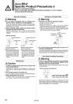
Maintenance Caution 1. In order to maintain good performance, operate with clean unlubricated air. If lubricated air, compressor oil or drainage, etc., enter the cylinder, there is a danger of sharply reducing the locking performance. 2. Do not apply grease to the piston rod. There is a danger of sharply reducing the locking performance. 3. Never disassemble the lock unit. It contains a heavy duty spring which is dangerous. There is also a danger of reducing the locking performance. Warning 1. Sizes MLU can hold the unlocked condition. 1) Remove the dust cover. 2) Supply air pressure of 0.2 MPa or more to the unlocking port, and set the lock ring to the perpendicular position. 3) Screw the unlocking bolt which is included (hexagon socket head screw o25, o32: M3 x 12 L, o40, o50: M4 x 16 L) into the lock ring to hold the unlocked condition. 2. To use the locking mechanism again, be sure to remove the unlocking bolt. The locking mechanism will not function with the unlocking bolt screwed-in. Remove the unlocking bolt according to the procedures described in the section “Preparing for Operation”. Holding the Unlocked State Warning 1. If two or more cylinders are used in close proximity, the auto switches may malfunction affected by the magnets built in the nearby cylinder. Please keep the cylinder mounting pitch larger than the values in the table below. When the mounting pitch is equal to or smaller than the value shown above, it has to be shielded by an iron plate or a magnetic shielding plate (Part No. MU-S025) purchased separately. Please contact SMC for more information. Auto Switch Handling Precautions Minimum cylinder mounting pitch Size L (d) (mm) 25 33 (10) 32 32 (5) 40 36 (5) 50 38 (0) Unlocking bolt Unlocking port Dust cover Manually Unlocking Warning 1. Do not perform unlocking when an external force such as a load or spring force is being applied. This is very dangerous because the cylinder will move suddenly. Release the lock after preventing cylinder movement with a lifting device such as a jack. 2. After confirming safety, operate the manual release following the steps shown below. Carefully confirm that no one is inside the load movement range, etc., and that there is no danger even if the load moves suddenly. Manually unlocking Extension locking direction Retraction locking direction 1) Remove the dust cover. 2) Screw a manual unlocking bolt (a conventional bolt of o25, o32: M3 x 0.5 x 25 L or more, o40, o50: M4 x 0.7 x 35 L or more) into the lock ring threads as shown above, and lightly push the bolt in the direction of the arrow (head side) to unlock. 1) Remove the dust cover. 2) Screw a manual unlocking bolt (a conventional bolt of o25, o32: M3 x 0.5 x 25 L or more, o40, o50: M4 x 0.7 x 35 L or more) into the lock ring threads as shown above, and lightly push the bolt in the direction of the arrow (rod side) to unlock. Locking direction Locking direction Manual unlocking bolt Lock ring Manual unlocking bolt Lock ring Series MLU Specific Product Precautions 3 Be sure to read before handling. Refer to front matter 39 for Safety Instructions and pages 3 to 12 for Actuator and Auto Switch Precautions. L d 982