3-p1653-1671-ml2b_en 7 / 20
10秒後にBOOKのページに移動します
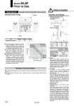
Type Allowable kinetic energy (J) ML2B25 0.43 ML2B32 0.68 ML2B40 1.21 傖 The piston speed will exceed the average speed immediately before locking. To determine the piston speed for the purpose of obtaining the kinetic energy of load, use 1.4 times the average speed as a guide. 傖 The relation between the speed and the load of the respective tube bores is indicated in the diagram on the right. Use the cylinder in the range below the line. 傖 Locking mechanism has to absorb not only kinetic energy of pay load but also thrust energy of cylinder when locking. Accordingly, to secure braking force there is a certain limit for pay load despite being within allowable kinetic energy. In the case of horizontal orientation, the solid line is the load limit. In the case of vertical orientation, the dotted line is the load limit. W SOL. 1 ON OFF OFF A B Stop SOL. 2 OFF ON OFF SOL. 3 ON ON OFF Handling of Technical Material 傖 For further positioning system, refer to “Instruction manual for positioning system with brake (rodless type)”. 傖 For further cylinder information, refer to “Instruction manual for Stroke Reading Rodless Cylinder with Brake”. Series ML2B Prior to Use Workpiece Guide ML2B Allowable Kinetic Energy (Model Selection With external guide) Allowable kinetic energy ML2B40 ML2B32 ML2B25 100 200 1000 1500 50 300 400 500 10 5 0.5 Piston speed (mm/s) Load weight (kg) Horizontal and lateral mounting Vertical mounting Caution on Handling Pneumatic Circuit Design 1. Operating pneumatic circuit [Horizontal and lateral mounting] [Vertical mounting] 2. Solenoid valve for driving and braking 3. Piping Piping length between cylinder ports and solenoid valve for driving should be less than 50 cm. When using system with brake, piping length between solenoid valve for braking and brake supply port should be less than 1 m. If longer, the brake function may be delayed when the cylinder position is held, for emergency stops or cylinder may eject at brake release. 4. Air balance Air balance on both pneumatic circuits mentioned above is made by supplying air pressure, to both sides of the piston when at intermediate stop. When mounting vertically the balance of load is kept by a regulator (1) decreases up-stream pressure. Use caution the piston rod may be lurched when the next motion gets started after the intermediate stops or commence the operation after the reverse motion gets done, unless the air balance is taken. It may result in degrading its accuracy. 5. Supply pressure Set supply pressure 0.3 to 0.5 MPa to brake release port. When supply pressure is below 0.3 MPa brake may not be released, when it is over 0.5 MPa brake life may be shortened. If line pressure is used directly as supply pressure, any fluctuation in pressure will appear in the form of changes in cylinder characteristics. Therefore, make sure to use a pressure regulator to convert line pressure into supply pressure for the solenoid valve for driving and the solenoid valve for braking. In order to actuate multiple cylinders at once, use a pressure regulator that can handle a large air flow volume and also consider installing an air tank. Solenoid valve for driving Solenoid valve for braking Regulator Horizontal and lateral mounting VFS25尰0 Vertical mounting VFS24尰0R VFS21尰0 AR425 Piping size ML2B25, 32 ML2B40 Bore size o4 or more Bore size o5 or more 1658