3-p1691-1700-cvqm_en@@@10 / 11
10bÐèBOOKäy[WèÖÛçÉñ
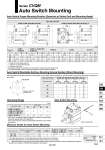
A W A B . Hs A B Series CVQM Auto Switch Mounting Operating Range Auto Switch Mounting Minimum Stroke for Auto Switch Mounting Auto Switch Proper Mounting Position (Detection at Stroke End) and Mounting Height Auto Switch Mountable Surface, Mounting Groove Number (Direct Mounting) The below table shows which surfaces of the cylinder an auto switch can be mounted on, and the number of grooves for the direct mounting style auto switch. o32, o40, o50, o63 D-M9ÞÙ/D-M9ÞÙW/D-M9ÞÙA/D-A9ÞÙ D-M9ÞÙV/D-M9ÞÙWV/D-M9ÞÙAV/D-A9ÞÙV Bore size (mm) 32 40 50 63 8 [13] 12 10 <15> 12.5 8 [13] 12 10 <15> 12.5 5 7.5 10.5 13.5 5 7.5 10.5 13.5 27 30.5 36.5 40 12 [17] 16 14 <19> 16.5 9 11.5 14.5 17.5 29 32.5 42 42 12 [17] 16 14 <19> 16.5 9 11.5 14.5 17.5 (mm) [ ]: Values for 5 mm stroke with o32 < >: Values for 10 mm stroke with o50 ( ): Values for the D-A93 . The negative indication in the table for W shows the mounting inside the cylinder body. . For the actual setting, check the operating condition of the auto switch and adjust. D-M9ÞÙ D-M9ÞÙA D-A9ÞÙ D-A9ÞÙV D-M9ÞÙW D-M9ÞÙV, D-M9ÞÙWV D-M9ÞÙAV A B A B .3 (.0.5) .5.5 (.3) .8.5 (.6) .11.5 (.9) A B W Hs 1 .1.5 .4.5 .7.5 W A B Hs 12 [17] 16 14 <19> 16.5 9 11.5 14.5 17.5 3 0.5 .2.5 .5.5 A B W D-A9ÞÙ, D-A9ÞÙV D-M9ÞÙ, D-M9ÞÙV D-M9ÞÙW, D-M9ÞÙWV D-M9ÞÙA, D-M9ÞÙAV Auto switch model Bore size (mm) 32 40 6 9.5 6 9.5 50 7 9.5 63 7.5 11.5 . Since this is a guideline including hysteresis, not meant to be guaranteed. (assuming approximately }30% dispersion) There may be the case it will vary substantially depending on the ambient environment. Bore size (mm) 32.1, 40 50.2, 63 D-A9ÞÙ 10 (5) 10 (mm) Number of auto switches mounted 1 2 .1 The outline dimensions for 5 mm stroke will be the same as those for 10 mm stroke. .2 The outline dimensions for 10 mm stroke will be the same as those for 15 mm stroke. .3 ( ): Mountable minimum stroke when the auto switch protrudes from the cylinder body end face and does not interfere with the space for the lead wire. (The figure on the right) Order separately for auto switches. D-A9ÞÙV 5 10 D-M9ÞÙ 10 (5) 10 (5) D-M9ÞÙV 5 5 D-M9ÞÙW D-M9ÞÙA 15 (10) 15 D-M9ÞÙWV D-M9ÞÙAV 10 15 Auto switch model D-M9ÞÙ(V), M9ÞÙW(V), M9ÞÙA(V), A9ÞÙ(V) Bore size (mm) A (Mounting groove number) B (Mounting groove number) C (Mounting groove number) D (Mounting groove number) 32 40 . ÞÝ (2) ÞÝ (2) ÞÝ (2) . ÞÝ (2) ÞÝ (2) ÞÝ (2) 50 . ÞÝ (2) ÞÝ (2) ÞÝ (2) 63 . ÞÝ (2) ÞÝ (2) ÞÝ (2) A C D B Port aperture Diagram seen from the piston rod Refer to page 2002. 1699 CVQ CVJÞÛ CVMÞÛ CV3 CVS1 MVGQ D-ÞÛ -XÞÛ CVQM