4-p0269-0296-crq2-cdrq2_en 12 / 29
10秒後にBOOKのページに移動します
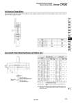
Size 10 15 20 30 40 L 13 16 22.5 24.5 28.5 Screw M4 M4 M6 M8 M8 Solid state switch Reed switch 10 15 20 30 40 90° 180° 360° 90° 180° 360° 90° 180° 360° 90° 180° 360° 90° 180° 360° 15 18 25 18.5 22.5 30.5 36 42 55.5 43 51 62 50 59.5 72.5 21.5 31 52.5 27 39.5 64.5 48.5 67.5 106 59 82 125.5 69 97.5 152 63° 52° 41° 32° 24° A 12° 9° 9° 7° 5° B 19 22 29 22.5 26.5 34.5 40 46 59.5 47 55 66 54 63.5 76.5 25.5 35 56.5 31 43.5 68.5 52.5 71.5 110 63 86 129.5 73 101.5 156 61° 47° 40° 29° 24° A 5° 4° 4° 2° 2° B Unit Used as Flange Mount The L dimensions of this unit are shown in the table below. When hexagon socket head cap bolt of the JIS standard is used, the head of the bolt will recess into the groove of actuator. Auto Switch Proper Mounting Position at Rotation End Operating range at proper mounting position (Lm/2) Operating range of single auto switch (Lm) Most sensitive position Size Rotating angle Operating angle θ m: The value of the individual switch’s movement range Lm as represented by an angle. Hysteresis angle: Value of the switch’s hysteresis as represented by an angle. Operating angle (θ m) Hysteresis angle Operating angle (θ m) Hysteresis angle Note) Since the above values are only provided as a guideline, they are not guaranteed. In the actual setting, adjust them after confirming the auto switch performance. L A B Series CRQ2 Compact Rotary Actuator Rack & Pinion Style 279 CRB2 -Z CRBU2 CRB1 MSU CRJ CRA1 -Z CRA1 CRQ2 MSQ MSZ CRQ2X MSQX MRQ D-