4-p0269-0296-crq2-cdrq2_en 15 / 29
10秒後にBOOKのページに移動します
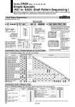
RQ2B Nil D None Built-in magnet 10 15 20 30 40 90 180 360 80° to 100° 170° to 190° 350° to 370° C D S P 20 90 C M9BW X How to order model with auto switches A 1 A 2 A13 A14 A24 A24 C 8 C30 C30 -X 6 C30 -X 6 . Combination 3 Types . Combination 4 Types Chart 1, 2 Chart 1 Chart 2, 5 Chart 2 . Combination of Applicable Chart A 1 A 2 A14 A14 A 2 A24 C11 C 7 C 8 C10 C30 C12 C30 -X 6 -X 6 C30 Chart 1, 2, 5 Chart 1, 2 Chart 2, 5 Chart 2, 5 . Combination of Applicable Chart A2 A24 C30 -X6 Size 10, 15 20, 30, 40 Air cushion None Nil Attached . Size C 10, 15 20, 30, 40 Port type Nil Nil TF TN TT M5 Rc 1/8 G 1/8 NPT 1/8 NPTF 1/8 Single shaft Double shaft S W XA 1 XA 2 XA 3 XA 4 XA 5 XA 6 XA 7 XA 8 XA 9 XA10 XA11 XA12 XA13 XA14 XA15 XA16 XA17 XA18 XA19 XA20 XA21 XA22 XA23 XA24 10, 15 20, 30, 40 10, 15 20, 30, 40 20, 30, 40 10, 15, 20, 30, 40 10, 15 10,15 10, 15, 20, 30, 40 10,15 10, 15 Symbol Description Top port Shaft type Upper Lower Applicable size Combination . Describes the combination available for corresponding shaft shapes. S W Chart 1. Combination between -XA尰 and -XA尰 (S, W shaft) XC 7 XC 8 XC 9 XC10 XC11 XC12 XC13 XC14 XC15 XC16 XC17 10, 15 20, 30, 40 Chart 2. Combination between -XA尰 and -XC尰 (Made to Order/ Details of -XC尰, refer to page 292.) 10, 15, 20, 30, 40 10, 15, 20, 30, 40 10, 15 XC18 XC19 XC20 XC21 XC22 XC30 XC69 20, 30, 40 . Chart 5. Refer to page 292 for combination available between -XC尰 and -XC尰. How to Order Combination Chart of Simple Specials for Tip End Shape Combination Chart of Made to Order Series CRQ2 (Size: 10, 15, 20, 30, 40) Simple Specials: -XA1 to -XA24: Shaft Pattern Sequencing I Shaft pattern sequencing is dealt with a simple made-to-order system. (Refer to front matter 32.) Please contact SMC for a specification sheet when placing an order. Shaft Pattern Sequencing I Applicable shaft type: S, W -XA1 to XA24 Built-in magnet Shaft type Size Pattern Thread type Refer to page 272 for “How to Order”products with auto switch. Rotating angle Air cushion Auto switch Refer to page 272 for the part no. of auto switches. Symbol for simple special, Made-to-Order products . When the number of combinations is 1 or 2, refer to chart 1 and 2. . Combination of XA is possible for up to 2 types. . Combination of -X6 (Shaft, parallel stainless spec) is available with all the types. Combination is available only when all the conditions are fulfilled among the combination chart above. Combination is available only when all the conditions are fulfilled among the combination chart above. . Combination of simple specials and Made-to-Order, it is possible for up to 4 types. Female thread at the end Female thread at the end Tip end of male thread Tip end of male thread Stepped round shaft Stepped round shaft Round shaft with steps and male thread Round shaft with steps and male thread Change of the length of standard chamfered face Change of the length of standard chamfered face Two-sided chamfer Two-sided chamfer Shaft through-hole Shaft through-hole and female thread Shaft through-hole and female thread Shaft through-hole and female thread Shortened shaft Shortened shaft Shortened shaft Reversed shaft Stepped round shaft with double-sided chamfer Stepped round shaft with double-sided chamfer Right-angle chamfer Double key Symbol Description Applicable size Combination XA1 to XA24 Symbol Description Applicable size Combination XA1 to XA24 Reversed shaft Change of rotating range Change in angle adjustable range 0° to 100° Change in angle adjustable range 90° to 190° Change of rotating range Without inner rubber bumper Fluorine grease Fluororubber seal Change in angle adjustable range 90° to 190° Symbol 282