4-p0269-0296-crq2-cdrq2_en 16 / 29
10秒後にBOOKのページに移動します
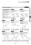
Machine female threads into the long shaft. The maximum dimension L1 is, as a rule, twice the thread size (Example) For M3: L1 = 6 . Applicable shaft types: S, W Machine female threads into the short shaft. The maximum dimension L2 is, as a rule, twice the thread size. (Example) For M4: L2 = 8 . Applicable shaft types: S, W The long shaft can be further shortened by machining male threads into it. (If shortening the shaft is not required, indicate “.” for dimension X.) . Applicable shaft types: S, W The short shaft can be further shortened by machining it into a stepped round shaft. (If shortening the shaft is not required, indicate “.” for dimension Y.) (If not specifying dimension C2, indicate “.” instead.) . Applicable shaft type: W . Equal dimensions are indicated by the same marker. The long shaft can be further shortened by machining it into a stepped round shaft with male threads. (If shortening the shaft is not required, indicate “.” for dimension X.) (If not specifying dimension C1, indicate “.” instead.) . Applicable shaft types: S, W The short shaft can be further shortened by machining male threads into it. (If shortening the shaft is not required, indicate “.” for dimension Y.) . Applicable shaft type: W The long shaft can be further shortened by machining it into a stepped round shaft. (If shortening the shaft is not required, indicate “.” for dimension X.) (If not specifying dimension C1, indicate “.” instead.) . Applicable shaft types: S, W . Equal dimensions are indicated by the same marker. The short shaft can be further shortened by machining it into a stepped round shaft with male threads. (If shortening the shaft is not required, indicate “.” for dimension Y.) (If not specifying dimension C2, indicate “.” instead.) . Applicable shaft type: W Additional Reminders 1. Enter the dimensions within a range that allows for additional machining. 2. SMC will make appropriate arrangements if no dimensional, tolerance, or finish instructions are given in the diagram. 3. The length of the unthreaded portion is 2 to 3 pitches. 4. Unless specified otherwise, the thread pitch is based on coarse metric threads. M3 x 0.5, M4 x 0.7, M5 x 0.8 M6 x 1 5. Enter the desired figures in the portion of the diagram. 6. XA1 to XA24 are the standard products that have been additionally machined. 7. Chamfer face of the parts machining additionally is C0.5. Size 10 15 20 30 40 Q1 M3 M3, M4 M3, M4 M3, M4, M5 M4, M5, M6 Size 10 15 20 30 40 Q2 M3 M3, M4 M3, M4 M3, M4, M5 M4, M5, M6 Size 10 15 X 9 to 18 10 to 20 L1 max X . 4 X . 4 Q1 M5 M6 Size 10 15 Y 7 to 9 8 to 10 L2 max Y . 2 Y . 3 Q2 M5 M6 Size 10 15 X 3 to 18 3 to 20 L1 max X . 2 X . 2 Size 10 15 Y 1 to 9 1 to 10 L2 max YY Size 10 15 X 8 to 18 9.5 to 20 L1 max X . 2 X . 2 Q1 M3, M4 M3, M4, M5 Size 10 15 L2 max YY Q2 M3, M4 M3, M4, M5 Symbol: A1 Symbol: A3 Symbol: A4 Symbol: A5 Symbol: A6 Symbol: A7 Symbol: A8 Symbol: A2 Y 6 to 9 7.5 to 10 (mm) (mm) D1 o3.5 to o4.9 o3.5 to o5.9 D2 o3.5 to o4.9 o3.5 to o5.9 Q1 = M Q1 = M Size 10, 15 Size 20, 30, 40 L1 + (3 x P) L1 = L1 + (3 x P) L1 = Q2 = M Q2 = M Size 10, 15 Size 20, 30, 40 L2 = L2 + (3 x P) L2 = L2 + (3 x P) Q1 = M X = L1 = Q2 = M Y = L2 = X = L1 = D1 = o C1 = C C1 Y = L2 = D2 = o C2 C2 = C Q1 = M X = L1 = C1 = C L1 - (3 x P) Q2 = M Y = L2 = C2 = C L2 - (3 x P) (mm) (mm) (mm) (mm) (mm) (mm) Shaft Pattern Sequencing I -XA1 to XA8 Symbol Simple Specials Series CRQ2 283 CRB2 -Z CRBU2 CRB1 MSU CRJ CRA1 -Z CRA1 CRQ2 MSQ MSZ CRQ2X MSQX MRQ D-