4-p0269-0296-crq2-cdrq2_en 17 / 29
10秒後にBOOKのページに移動します
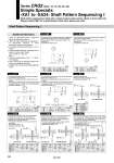
Symbol: A9 Symbol: A11 Symbol: A12 Symbol: A13 Symbol: A10 Symbol: A14 Symbol: A15 Symbol: A16 The long shaft can be further shortened by machining a double-sided chamfer on to it. . Since L1 is a standard chamfer, dimension E1 is 0.5 or more. (If altering the standard chamfer and shortening the shaft are not required, indicate “.” for both the L1 and X dimensions.) . Applicable shaft types: S, W The short shaft can be further shortened by machining a double-sided chamfer on to it. . Since L2 is a standard chamfer, dimension E2 is 0.5 or more. (If altering the standard chamfer and shortening the shaft are not required, indicate “.” for both the L2 and Y dimensions.) . Applicable shaft type: W Shaft with through-hole Minimum machining diameter for d1 is 0.1. . Applicable shaft types: S, W Size 10 15 X 8 to18 10 to 20 L1 {10 . (18 . X) } to (X . 2) {10 . (20 . X) } to (X . 2) Size 10 15 Y 3 to 9 3 to 10 L2 6 . (9 . Y) to Y 7 . (10 . Y) to Y Size 10 15 Y 3 to 9 3 to10 L4 max YY L2 6 . (9 . Y) to Y 7 . (10 . Y) to Y Size 10 15 X 8 to 18 10 to 20 L3 max X . 2 X . 2 L1 {10 . (18 . X)} to (X . 2) {10 . (20 . X)} to (X . 2) Size d1 10 15 20 30 40 10 o2.5 ... 15 o2.5 o3.3 .. 20 o2.5 o3.3 .. 30 . o3.3 o4.2 . 40 .. o4.2 o5 M3 x 0.5 M4 x 0.7 M5 x 0.8 M6 x 1 10 o2.5 ... 15 o2.5 o3.3 .. 20 o2.5 o3.3 .. 30 . o3.3 o4.2 . 40 .. o4.2 o5 M3 x 0.5 M4 x 0.7 M5 x 0.8 M6 x 1 10 o2.5 ... 15 o2.5 o3.3 .. 20 o2.5 o3.3 .. 30 . o3.3 o4.2 . 40 .. o4.2 o5 M3 x 0.5 M4 x 0.7 M5 x 0.8 M6 x 1 Size Size Size A special end is machined onto the long shaft, and a through-hole is drilled into it. Female threads are machined into the through-hole, whose diameter is equivalent to the pilot hole diameter. . The maximum dimension L1 is, as a rule, twice the thread size. (Example) For M3: L1 = 6 . Applicable shaft types: S, W A special end is machined onto the short shaft, and a through-hole is drilled into it. Female threads are machined into the through-hole, whose diameter is equivalent to the pilot hole diameter. . The maximum dimension L2 is, as a rule, twice the thread size. (Example) For M4: L2 = 8 . Applicable shaft types; S, W A special end is machined onto both the long and short shafts, and a through-hole is drilled into both shafts. Female threads are machined into the through-holes, whose diameter is equivalent to the diameter of the pilot holes. . The maximum dimension L1 is, as a rule, twice the thread size. (Example) For M5: L1 = 10 . Applicable shaft types: S, W . Equal dimensions are indicated by the same marker. The long shaft can be further shortened by changing the length of the standard chamfer on the long shaft side. (If shortening the shaft is not required, indicate “.” for dimension X.) . Applicable shaft types: S, W The short shaft can be further shortened by changing the length of the standard chamfer. (If shortening the shaft is not required, indicate “.” for dimension Y.) . Applicable shaft type: W Thread Thread Thread o2 to o3 o2 to o4 o2.5 to o3.5 o3 to o5.5 o4 to o7 (mm) (mm) X = L1 = Y = L2 = X = L3 = E1 = E3 = L1 = Y = L4 = L2 = E2 = E4 = Size 10, 15 Size 20, 30, 40 Size 10, 15 Size 20, 30, 40 Size 10, 15 Size 20, 30, 40 Size 10, 15 Size 20, 30, 40 (mm) (mm) (mm) (mm) (mm) (mm) Shaft Pattern Sequencing I Series CRQ2 (Size: 10, 15, 20, 30, 40) Simple Specials: -XA1 to -XA24: Shaft Pattern Sequencing I Shaft pattern sequencing is dealt with a simple made-to-order system. (Refer to front matter 32.) Please contact SMC for a specification sheet when placing an order. Additional Reminders 1. Enter the dimensions within a range that allows for additional machining. 2. SMC will make appropriate arrangements if no dimensional, tolerance, or finish instructions are given in the diagram. 3. The length of the unthreaded portion is 2 to 3 pitches. 4. Unless specified otherwise, the thread pitch is based on coarse metric threads. M3 x 0.5, M4 x 0.7, M5 x 0.8 M6 x 1 5. Enter the desired figures in the portion of the diagram. 6. XA9 to XA24 are the standard products that have been additionally machined. 7. Chamfer face of the parts machining additionally is C0.5. d1 = o d1 = o Q1 Q1 L1 L1 Q1 = M Q1 = M L1 = L1 = Q2 = M Q2 = M L2 = L2 = Q1 = M Q1 = M L1 = L1 = 284