4-p0269-0296-crq2-cdrq2_en 22 / 29
10秒後にBOOKのページに移動します
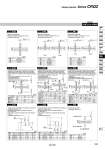
Symbol: A39 Symbol: A40 Symbol: A41 Symbol: A42 Symbol: A43 Symbol: A44 Symbol: A45 Symbol: A46 Shaft with through-hole Minimum machining diameter for d1 is 0.1. . Applicable shaft type: Y Shaft with through-hole Minimum machining diameter for d1 is 0.1. . Applicable shaft types: K, T Shaft with through-hole Minimum machining diameter for d1 is 0.1. . Applicable shaft types: J, X, Z The long shaft can be further shortened by machining a middle-cut chamfer into it. (If shortening the shaft is not required, indicate “.” for dimension X.) (The position is that of the standard flat at the keyway portion.) . Applicable shaft types: J, K, T The short shaft can be further shortened by machining a middle-cut chamfer into it. (If shortening the shaft is not required, indicate “.” for dimension Y.) (The position is that of the standard flat at the keyway portion.) . Applicable shaft type: K d1 o2.5 to o3.5 o3 to o5.5 o4 to o7 Size 10 15 20 30 40 d1 o2 to o3 o2 to o4 o2.5 to o6 o3 to o8 o4 to o10 Size 10 15 20 30 40 d1 o2 to o3 o2 to o4 o2.5 to o5 o3 to o7 o4 to o8 Size Thread M3 x 0.5 M4 x 0.7 M5 x 0.8 M6 x 1 Size Thread M 3 x 0.5 M 4 x 0.7 M 5 x 0.8 M 6 x 1 M 8 x 1.25 M10 x 1.5 Rc 1/8 Size Thread M3 x 0.5 M4 x 0.7 M5 x 0.8 M6 x 1 M8 x 1.25 10 o2.5 . . . . 15 o2.5 o3.3 . . . 20 o2.5 o3.3 o4.2 . . 30 . 40 . . Size 10 15 20 30 40 X 6 to 18 6.5 to 20 9.5 to 30 11.5 to 32 12.5 to 36 W1 L1 max X . 2 X . 2 X . 2.5 X . 3 X . 3 L3 max L1 . 1 L1 . 1 L1 . 2 L1 . 2 L1 . 2 Size 10 15 20 30 40 Y 4 to 18 4.5 to 20 6.5 to 30 8.5 to 32 9.5 to 36 W2 L2 max Y Y Y Y Y L4 max L2 . 1 L2 . 1 L2 . 2 L2 . 2 L2 . 2 o4.2 o5 o6.8 o3.3 o4.2 o5 . 0.5 to 1.5 0.5 to 1.5 1 to 2 1 to 2 1 to 2 0.5 to 1.5 0.5 to 1.5 1 to 2 1 to 2 1 to 2 A special end is machined onto both the long and short shafts, and a through-hole is drilled into both shafts. Female threads are machined into the through-holes, whose diameter is equivalent to the diameter of the pilot holes. . The maximum dimension L1 is, as a rule, twice the thread size. . Applicable shaft type: Y . Equal dimensions are indicated by the same marker. 20 o2.5 o3.3 . . 30 . o3.3 o4.2 . 40 . . o4.2 o5 A special end is machined onto both the long and short shafts, and a through-hole is drilled into both shafts. Female threads are machined into the through-holes, whose diameter is equivalent to the diameter of the pilot holes. . The maximum dimension L1 is, as a rule, twice the thread size. . Applicable shaft types: K, T . Equal dimensions are indicated by the same marker. A special end is machined onto both the long and short shafts, and a through-hole is drilled into both shafts. Female threads are machined into the through-holes, whose diameter is equivalent to the diameter of the pilot holes. . The maximum dimension L1 is, as a rule, twice the thread size. . Applicable shaft types: J, X, Z . Equal dimensions are indicated by the same marker. X = L1 = L3 = W1 = Y = L2 = L4 = W2 = Size 20 30 40 (mm) (mm) (mm) (mm) (mm) (mm) (mm) (mm) -XA31 to XA48 Long shaft side Short shaft side Size 20, 30, 40 X 17 to 30 18 to 32 18.5 to 36 Size 20 30 40 (mm) Symbol: A48 Shorten the long shaft. . Applicable shaft type: Y 10 o2.5 . . . . . . 15 o2.5 o3.3 . . . . . 20 30 . 40 . . o4.2 o5 o6.8 o8.5 o8.2 o3.3 o4.2 o5 o6.8 . . . . . o2.5 o3.3 o4.2 o5 d1 = o T axis K axis d1 = o d1 = o J axis Z axis d1 = o d1 = o Q1 = M Q1 L1 L1 = Q1 = M Q1 T axis L1 L1= Q1 = M Q1 K axis L1 L1 = Q1 = M Q1 Q1 Q1 = M J axis Z axis L1= L1 L1 L1 = X = Symbol Simple Specials Series CRQ2 289 CRB2 -Z CRBU2 CRB1 MSU CRJ CRA1 -Z CRA1 CRQ2 MSQ MSZ CRQ2X MSQX MRQ D-