4-p0269-0296-crq2-cdrq2_en 27 / 29
10秒後にBOOKのページに移動します
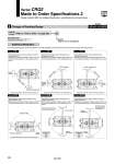
CRQ2B CDRQ2B Symbol: C8 Symbol: C9 Symbol: C10 Symbol: C11 Symbol: C18 Symbol: C19 Angle adjustment at the rotation starting point and the end point are at ±5°. Rotating range is changed. Rotation angle is at 90° ±10°. The rotation starting point is on the perpendicular line (down). Angle adjustment at the rotation starting point and the end point are at ±5°. Rotating range is changed. Rotation angle is at 180° ±10°. The rotation starting point is on the horizontal line (left). Angle adjustment at the rotation starting point and the end point are at ±5°. Rotating range is changed. Rotation angle is at 90° ±10°. The rotation starting point is on the horizontal line (left). Angle adjustment at the rotation starting point and the end point are at ±5°. Rotating range is changed. Rotation angle is at 180° ±10°. The rotation starting point is on the perpendicular line (down). Angle adjustment at the rotation starting point and the end point are at ±5°. Rotating range is changed. Rotation angle is at 90° ±10°. The rotation starting point is on the perpendicular line (up). Angle adjustment at the rotation starting point and the end point are at ±5°. Rotating range is changed. Rotation angle is at 180° ±10°. The rotation starting point is on the perpendicular line (up). Refer to “How to Order” on page 282. X C8 Symbol -XC8 to XC11, XC18/XC19 Operating size 20 30 40 Operating size 20 30 40 The figure shows the view from the long shaft end. The figure shows the view from the long shaft end. The figure shows the view from the long shaft end. The figure shows the view from the long shaft end. Additional Reminders The rotation starting point shows the positions of one flat chamfering and the key groove when pressurized to the connecting port (B). 2 Change of Rotating Range -XC8 to XC11, XC18/XC19 Specifications Applicable shaft type S, W, Y Series CRQ2 Made to Order Specifications 2 Please contact SMC for detailed dimensions, specifications and lead times. Rotation starting point B A 5° 5° 5° 5° B A End of rotation 5° 5° 5° B A End of rotation Rotation starting point 5° 5° 5° 5° End of rotation Rotation range Rotation range Rotation starting point Rotation range Rotation starting point End of rotation A B 5° 5° 5° 5° End of rotation Rotation starting point B A 5° 5° 5° 5° B A 5° 5° 5° 5° The figure shows the view from the long shaft end. Rotation range Rotation range The figure shows the view from the long shaft end. Rotation range End of rotation Rotation starting point Symbol 294