4-p0269-0296-crq2-cdrq2_en 28 / 29
10秒後にBOOKのページに移動します
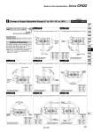
3 Change of Angle Adjustable Range (0° to 100°, 90° to 190°) -XC12 to XC17, XC20/XC21 CRQ2B CDRQ2B Symbol: C14 Symbol: C15 Symbol: C16 Symbol: C17 Symbol: C20 Symbol: C21 Symbol: C12 Symbol: C13 The rotation angle can be adjusted between 0° and 100°. The rotation angle can be adjusted between 0° and 100°. The rotation angle can be adjusted between 0° and 100°. The rotation angle can be adjusted between 0° and 100°. The rotation angle can be adjusted between 90° and 190°. The rotation angle can be adjusted between 90° and 190°. The rotation angle can be adjusted between 90° and 190°. The rotation angle can be adjusted between 90° and 190°. Additional Reminders The rotation starting point is the position of the flat and the key groove when the actuator is pressurized through connection port B. There are no air cushion effects in the rotating ranges of 70° or 160° shown in the diagram. . Only XC12 and XC16 are compatible with shaft types X, Z, T, J and K. Refer to “How to Order” on page 282. Symbol -XC12 to XC17, XC20/XC21 X C12 Size 10 15 20 30 40 Lmax 15 18 24 27 31.5 Size 10 15 20 30 40 Lmax 15 18 24 27 31.5 Size 10 15 20 30 40 Lmax 15 18 24 27 31.5 Size 10 15 20 30 40 Lmax 15 18 24 27 31.5 Size 10 15 20 30 40 Lmax 15 18 24 27 31.5 Size 10 15 20 30 40 Lmax 15 18 24 27 31.5 Size 20 30 40 Lmax 24 27 31.5 Size 20 30 40 Lmax 24 27 31.5 Specifications Applicable shaft type S, W, Y, X., Z., T., J., K. Operating size 20 30 40 Operating size 20 30 40 Made to Order Specifications Series CRQ2 The figure shows the view from the long shaft end. The figure shows the view from the long shaft end. The figure shows the view from the long shaft end. The figure shows the view from the long shaft end. The figure shows the view from the long shaft end. The figure shows the view from the long shaft end. The figure shows the view from the long shaft end. The figure shows the view from the long shaft end. L L A B A B Rotation starting point End of rotation 10° 10° 70° Rotation range Rotation starting point End of rotation 10° 10° 70° Rotation range L L A B Rotation starting point End of rotation 10° 10° 70° Rotation range A B Rotation starting point End of rotation 10° 160° Rotation range 10° L A B Rotation starting point End of rotation 10° 10° 70° Rotation range L A B Rotation starting point End of rotation 10° 10° 160° Rotation range L A B Rotation starting point End of rotation 10° 10° 160° Rotation range L A B End of rotation 10° Rotation starting point 10° 160° Rotation range Symbol 295 CRB2 -Z CRBU2 CRB1 MSU CRJ CRA1 -Z CRA1 CRQ2 MSQ MSZ CRQ2X MSQX MRQ D-