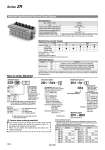
Individual Spacer Manifold Specifications/Vacuum Pump System How to Order Manifold Specifications Max. number of units Port Port size Basic mass for one station is 0.28kg. Additional mass per one station is 0.12 kg. 6 stations Supply port location Manifold Port Left Right PV PS PD PV PS PD L (Left side) R (Right side) B (Both sides) Manifold Vacuum/Air Supply Function PS PV Port ZR1-R1 to R16 Part no. PD PE ZR1-R1 -R2 -R3 -R4 -R5 -R6 -R7 -R8 R1 R2 R3 R4 R5 R6 R7 R8 PS PS PS PS PD PD PD PD PE PE PE PE ZR1-R9 -R10 -R11 -R12 -R13 -R14 -R15 -R16 R9 R10 R11 R12 R13 R14 R15 R16 PS PS PS PS PV PV PV PV PV PV PV PV PD PD PD PD PE PE PE PE Example 1) ZZR106-R ....................... 1 pc. (Manifold base only) .ZR100-K15MZ-EC ........ 5 pcs. (Unit) .ZR1-BM1 ...................... 1 pc. (Blank plate) .ZR1-R1-3 ...................... 1 pc. (Individual spacer) Nil F G Note) Rc T NPTF 1 6 01 06 R L B Port location Thread type Stations ZZR1 06 ZR1 RV3 1 1 6 A ZR1 R1 1 1 station only 6 stations only 1 6 All stations 1 station only 6 stations only All stations A R16 ZR1 BM1 M5 M5 1 8 (Rc, NPTF, G) 1 2 (Rc, NPTF, G) Note) When using 3 or more stations with ZR100 manifold, utilize PV port as suction on both sides. Vacuum supply to PV port. Air supply to port. BLANK plug attached to port. Note) BLANK plug is attached on all ports of valve unit. Possible to set the pilot valve air supply pressure individually Possible to set the release valve supply pressure individually Possible to set the pilot valve exhaust individually Possible to set the external vacuum pressure individually Individual spacer is used when the connecting port of each unit is not common for the manifold connecting port. Mixed specifications of common and individual unit connecting ports for each unit is possible on manifolds with this individual spacer. Arrangement (Right valve station which is looked from valve side is first station.) Arrangement (Right valve station which is looked from valve side is first station.) . When the spacers are attached to the specified locations, specify all spacers. . When the spacers are attached to the specified locations, specify all spacers. Example 2) Attached to the first and third stations .ZR1-RV3-1 .ZR1-RV3-3 Fill the number Example 4) Attached to the first and third stations .ZR1-R1-1 .ZR1-R1-3 With reference from valve side, the third station from right side Left side Right side Both sides . Viewed from the front side of valve unit, confirm the port location on the right and/or left side. The asterisk denotes the symbol for assembly. Prefix it to the ejector part numbers to be mounted. When it is not added, the manifold base and ejector are shipped separately. Note ) The thread ridge shape is compatible with the G thread standard (JIS B 0202), but other shapes are not conforming to ISO16030 and ISO1179. Caution when ordering manifold Refer to (About individual spacer.) Refer to Example 1). Manifold supply or valve unit supply can be selectable for each port. In the right table, ports with the symbol mean that they are manifold supply, while others are individual supply from the valve unit. Symbols in the right table are printed on the surface of individual spacers. About individual spacers Common vacuum pressure supply (PV) port Common pilot pressure supply (PS) port Common release pressure supply (PD) port Common exhaust (EXH) port Weight (Manifold bases only) Part no. Symbol Part no. Symbol .ZR1-RV3-A ・・・ 2 Example 3) Attached to all stations. Series ZR 1014