4-p1175-1267-zp2_en 74 / 106
10秒後にBOOKのページに移動します
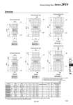
M1 M1 M2 M2 H.2 H.1 H.1 H.1 H.1 H.1 H.1 H.2 H.2 H.2 H.2 H.2 M2 M1 (L4) L1 L3.3 L2 (L4) L1 M2 L1 L3 L2 (L4) M2 L2 (L4) M1 M2 M1 L1 L2 L3.3 (L4) M1 L2 L1 L3 (L4) L3 L2 L1 L3 oD oD No.0.8 No.0.8 No.0.8 No.0.8 No.0.8 No.0.8 Vacuum generator side Pad side Vacuum generator side Pad side Vacuum generator side Vacuum generator side Vacuum generator side Vacuum generator side Pad side Pad side Pad side Pad side ZP2V-A5-尰 ZP2V-A8-尰 ZP2V-B5-尰 ZP2V-B6-尰 ZP2V-A01-尰 ZP2V-AN1-尰 ZP2V-AG1-尰 ZP2V-B01-尰 ZP2V-BN1-尰 ZP2V-BG1-尰 Model M1 M2 L1 L2 L3 L4 H (Width across flat) oD W (g) ZP2V-A5-尰 ZP2V-A8-尰 ZP2V-A01-尰 ZP2V-AG1-尰 ZP2V-AN1-尰 ZP2V-B5-尰 ZP2V-B6-尰 ZP2V-B01-尰 ZP2V-BG1-尰 ZP2V-BN1-尰 M5 x 0.8 M8 x 1.25 R1/8 G1/8 NPT1/8 M5 x 0.8 M6 x 1 Rc1/8 G1/8 NPT1/8 M5 x 0.8 M8 x 1.25 Rc1/8 G1/8 NPT1/8 M5 x 0.8 M6 x 1 R1/8 G1/8 NPT1/8 3.4 5.9 3.1 5.1 3.2 5.5 5 6.2 8 6.9 4.5 8 6.2 8 6.9 3.4 4.5 3.1 5.1 3.2 14.7 20.1 22.6 22.5 23.3 16.6 16.2 23.5 23.4 24.2 18.1 26 25.7 27.6 26.5 20 20.7 26.6 28.5 27.4 8 12 12 13 12 8 8 12 13 12 . . . 14 . . . . 14 . 6 18 18 23 23 7 7 19 24 20 Tightening torque (N・m) Note) 1.0 to 1.5 5.5 to 6.0 7.0 to 9.0 5.5 to 6.0 7.0 to 9.0 1.0 to 1.5 2.0 to 2.5 7.0 to 9.0 5.5 to 6.0 7.0 to 9.0 (mm) Dimensions .1 The place at the vacuum generator side where the tool is applied. .2 The place at the pad side where the tool is applied. .3 Referential dimensions after the R, NPT thread is screwed. Note) When mounting and removing the product, apply a wrench or torque wrench to the place shown in Figure. When mounting, tighten to the torque specified in the table. Vacuum Saving Valve Series ZP2V 1239 ZP3 ZP2 ZP ZPT ZPR XT661 ZP2V