5-p0541-0584-ag_en 45 / 45
10秒後にBOOKのページに移動します
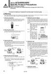
X Procedure for replacing or changing the mounting angle of a pressure gauge Warning When replacing a pressure gauge and/or changing the mounting angle, release the inlet and outlet pressure completely. It is dangerous to replace the pressure gauge or change the mounting angle while it is under pressure. 1. Advance preparation Keep the handle unlocked and completely loosened. The unlocked condition of the handle can be visually confirmed by the “Orange line” shown near the bottom of the handle. 2. Removing the handle To remove the handle, align the 傈 mark on the handle and the 傣 mark on the bonnet and then pull the handle. 3. Removing the clip When the 傣 mark on the bonnet and the 傈 mark on the pressure regulator guide are alligned, the clip can be seen from the side view of the bonnet. The clip can be picked and removed with tweezers. . When adjusting the mark, turn the pressure regulator guide clockwise for adjustment. 4. Removing the pressure gauge Pull the pressure gauge out by holding the outer edge of the dial. . Do not touch the internal mechanical portion (shown inside the dotted box). Accuracy of the pressure gauge may be adversely affected. 6. Setting the clip Insert the clip in the side of the bonnet when the 傈 mark on the pressure regulator guide and the 傣 mark on the bonnet are aligned. When inserting and setting the clip, use an instrument with a narrow tip, such as tweezers. Note 1) The clip is slightly tapered towards its tip to prevent it from being released. Set the clip by slightly opening its tip. Note 2) When the clip cannot easily be set, the cause may be as follows: (1) The pressure regulator screw might have been in a lower position than then the current one. (The pressure regulator screw may reach a lower position if the pressing force of the pressure regulator screw is excessively applied. This occurs because there is a clearance between the pressure regulator nut and pressure spring, when the pressure regulator screw is loosened completely.) (2) The pressure gauge is not firmly set. Countermeasures ..... Refer to 5 “Setting the pressure gauge”. 7. Setting the handle Finished when the handle is set. Table 1. Clearance Dimensions X dimension (reference value) ARG30 AWG30 ARG40 AWG40 ARG20 AWG20 2.6 mm 3.3 mm 3.3 mm Orange mark 5. Setting the pressure gauge After the mounting angle is adjusted as required, hold the outer edge of the pressure gauge dial and gently press down. For reference, the required clearance between the bottom of the dial and the top of the pressure regulator guide is shown in table 1. Note 1) When the pressure gauge cannot be easily positioned, slightly rotate it. (The cog from the planet gear of the pressure regulator guide may be caught vertically in the cog from the sun gear which is mounted and integrated with the pressure gauge) Note 2) Position the pressure gauge to the very bottom. Note 3) Attached to the tip of the pressure gauge is an O-ring with grease applied to it. Please use caution to prevent particles and/or dust from entering the pressure gauge when it is set. Otherwise, they may cause air leakage. Orange mark 傈 mark 傣 mark Bonnet Outer edge Internal mechanical portion Pressure regulator guide Bonnet side view Bonnet 傈 mark Clip 傣 mark Pressure regulator guide 傈 mark Clip 傣 mark Bonnet Bonnet side view 584 Series ACG/ARG/AWG Specific Product Precautions Be sure to read before handling. Refer to front matter 43 for Safety Instructions and pages 365 to 369 for F.R.L. Precautions.