5-p0541-0584-ag_en 5 / 45
10秒後にBOOKのページに移動します
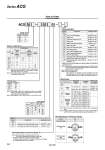
MPa KCOL to HSUP MPa KCOL to HSUP IN OUT OUT IN Regulator with Built-in Pressure Gauge ACG 30 03 G1 Body size Model combination Nil A B C D Symbol (1) . (1) (1) . (2) . (2) (3) . (3) (2) . . . . (1) . . (1) . . . (2) (2) Air filter Lubricator Filter Regulator with Built-in Pressure Gauge Mist separator Combination Thread type Symbol Nil N(3) F(4) Type Rc NPT G Port size Mounting angle of pressure gauge °0 Option Applicable model . ACG20 to 40 ACG30, 40 Symbol Nil C D Description . Float type auto-drain (Normally closed) Float type auto-drain (Normally open) Semi-standard . 0.02 to 0.2 MPa setting Metal bowl Lubricator with drain cock Nylon bowl Metal bowl with level gauge With bowl guard Filter case with drain guide Non-relieving type Flow direction: Right to left Drain cock with barb fitting: o6 x o4 nylon tubing Name plate and pressure gauge in imperial units (psi), caution plate for bowl (psi . °F) Regulator with upward facing handle . ACG20 to 40 ACG20 to 40 ACG20 to 40 ACG20 to 40 ACG30, 40 ACG20 ACG20 to 40 ACG20 to 40 ACG20 to 40 ACG30, 40 ACG20 to 40 ACG20 to 40 Nil 1 2 3 6 8 C J N R W Y Z Attachment Mounting Angle of Pressure Gauge Symbol Nil K S V Description Check valve Pressure switch Residual pressure relief 3 port valve Attachment mounting position Applicable model ACG20 to 40 ACG20A to 40A ACG20 to 40 ACG20B to 40B ACG20C to 40C ACG20 to 40 ACG20A to 40A ACG20B to 40B ACG20C to 40C ACG20D to 40D AF + ARG + [K] + AL AWG + [K] + AL AF + ARG + [S] + AL AF + [S] + ARG AF + AFM + [S] + ARG AF + ARG + AL + [V] AWG + AL + [V] AF + ARG + [V] AF + AFM + ARG + [V] AWG + AFM + [V] Port size for intermediate air release ACG20: 1/8 ACG30: 1/4 ACG40: 3/8 Note 6) When more than one attachment is required, order in alphabetical order. Note 7) Pressure switch cannot be mounted on the inlet and outlet sides of an ARG with an upward facing handle (optional specification: -Y). Note 1) Wall mount is not available for size 20 regulator with downward facing handle in B combination. Contact SMC when wall mount is needed. Note 2) The number inside ( ) indicates the combination order counted from the inlet side. Note 3) Drain guide is NPT1/8 for ACG20 and NPT1/4 for ACG30 and 40. Auto-drain port is provided with o3.8" One-touch fitting (applicable to ACG30 and 40). Note 4) Drain guide is G1/8 for ACG20 and G1/4 for ACG30 and 40. How to Order Symbol Description Applicable model Note 5) Mounting angle of pressure gauge is G1 only. If other mounting angles are needed, contact SMC. . Possible to change to the optional mounting angles. For details, refer to page 584, “Procedure for replacing or changing the mounting angle of a pressure gauge”. Symbol 01 02 03 04 Port size 1/8 1/4 3/8 1/2 20 . . 30 . . 40 . Body size Symbol 20 30 40 Port size 1/8 3/8 1/2 (8) (9) (7) (10) . When more than one specification is required, indicate in ascending alphanumeric order. Note 8) Adjusting spring and pressure gauge (full-span 0.3 MPa) are different from those for the standard specification. Outlet pressure may increase by 0.2 MPa or more. Note 9) Without a valve function. Note 10) For thread type NPT. This product is for overseas use only according to the new Measurement Law. (The SI unit type is provided for use in Japan.) Both MPa and psi are used for the pressure switch unit. (1) 0° Symbol G1 Mounting angle Mounting angle view Mounting angle view (-R specification) 544 Series ACG