6-p0564-0580-as-fm_enҒ@Ғ@Ғ@2 / 18
10•bҢгӮЙBOOKӮМғyҒ[ғWӮЙҲЪ“®ӮөӮЬӮ·
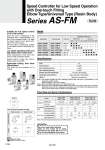
Model Flow Rate and Sonic Conductance Port size Applicable tubing O.D. 3.2 4 6 8 10 1/8" 5/32" 3/16" 1/4" 5/16" 3/8" Symbol Flow Direction Symbols on Body Meter-out type Meter-in type Elbow type Universal type AS12рӯ1FM-M5 AS22рӯ1FM-01 AS22рӯ1FM-02 AS12рӯ1FM-U10/32 AS22рӯ1FM-N01 AS22рӯ1FM-N02 AS13рӯ1FM-M5 AS23рӯ1FM-01 AS23рӯ1FM-02 AS13рӯ1FM-U10/32 AS23рӯ1FM-N01 AS23рӯ1FM-N02 M5 x 0.8 R 1/8 R 1/4 10-32 UNF NPT 1/8 NPT 1/4 Metric size Inch size RoHS Made to Order (Refer to page 565 for details.) Speed Controller for Low Speed Operation with One-touch Fitting Elbow Type/Universal Type (Resin Body) Series AS-FM Suitable for low speed control at 10 to 50 mm/sec Since the sonic conductance of the controlled flow is approximately 1/10 that of the standard model, it is ideal for speed control of low speed cylinders at 10 to 50 mm/sec. The dual type is particularly suitable for low speed control of small bore cylinders. Low speed operating stroke and high speed return stroke drive Sonic conductance of free flow is the same as that of standard model. Speed control is easy, and uniform speed control is possible. Applicable tubing: Inch sizes standardized Inch sizes are now available for all models. Specifications Fluid Proof pressure Max. operating pressure Mini. operating pressure Ambient and fluid temperature Applicable tubing material (1) Option (2) Air 1.5 MPa 1.0 MPa 0.1 MPa .5 to 60ҒӢC (No freezing) Nylon, Soft nylon, Polyurethane With seal, Round lock nut Note 1) Use caution regarding the max. operating pressure when soft nylon or polyurethane, or soft polyurethane tubing is used. (Refer to pages 411 and 412 for details.) Note 2) M5 and 10-32UNF type ports are not available with seal. Note 3) Brass parts are all electroless nickel plated. The lock nut of the meter-out type is zinc chromate plated (the round lock nut is electroless nickel plated), then, the handle of the M5 type and the lock nut of the meter-in type are black zinc chromate plated. Be sure to read before handling. Refer to front matter 56 for Safety Instructions and pages 468 to 471 for Flow Control Equipment Precautions. Caution Symbol Indication symbol o1/8",o5/32",o3/16",o1/4" o3/16",o1/4" o5/16" Tubing O.D. o3.2,o4 o1/8",o5/32" 180 0.54 o6,o8 230 0.7 o4 o5/32" 260 0.8 o6 o3/16" 390 1.2 o8,o10 460 1.4 Note) Flow rate values are measured at 0.5 MPa and 20ҒӢC. Model AS12рӯ1FM AS13рӯ1FM o3.2,o4,o6 7 0.02 0.2 100 0.3 0.4 AS22рӯ1FM-рӯ01 AS23рӯ1FM-рӯ01 AS22рӯ1FM-рӯ02 AS23рӯ1FM-рӯ02 Metric size Inch size Air flow (L/min(ANR)) Sonic conductance dm3/(s.bar) Critical pressure ratio Flow rate (L/min(ANR)) Sonic conductance dm3/(s.bar) Critical pressure ratio o1/4",o5/16" o3/8" 38 0.12 0.3 0.3 12 0.04 0.25 0.2 Controlled flow Free flow A 564