6-p0846-0850-z-ise1_en 5 / 6
10秒後にBOOKのページに移動します
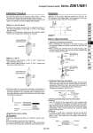
Compact Pressure Switch Series ZSE1/ISE1 ON OFF Caution Calibration Procedure SE1(L)- -14/-15/-18/-19 IZ . Set the ON-pressure by the pressure setting trimmer. Turning clockwise can set the high pressure/high vacuum pressure. . In the event of setting, use a flat head screwdriver suited for the groove of a trimmer, and rotate it lightly with a fingertip. . Switches with variable hysteresis can be adjusted by means of the HYS potentiometer in the range 1 to 10% of the setting pressure range. . Readjust the ON-pressure setting when the hysteresis setting trimmer was changed after setting the ON pressure. Hysteresis setting trimmer Pressure setting trimmer SET Indicator light HYS SE1(L)- 16/-17 . With pressure setting trimmer 1 (SET 1), OUT 1 (Black lead wire, Red LED) can be set. . With pressure setting trimmer 2 (SET 2), OUT 2 (White lead wire, Green LED) can be set. IZ Pressure setting trimmer 2 Pressure setting trimmer 1 SET1 Indicator light SET2 Set point Supply pressure Atmospheric pressure 0 Unsteady adsorption Non adsorption Steady adsorption High vacuum . Regarding the pressure setting . Set the possible min. pressure for adsorption confirmation. If setting the pressure lower than that, switch becomes ON in case that adsorption is not completely done. If setting the pressure higher than that, switch does not become ON even though it may absorb workpieces. Observe the following precautions for setting the vacuum pressure: Use your fingertips to gently turn the screwdriver. Do not use a screwdriver with a large grip or with a tip that does not fit into the trimmer groove because this could strip the groove. Hysteresis Hysteresis is the pressure difference between the ON and the OFF pressure of the output signal. The set pressure is the pressure selected to switch from OFF to ON condition. Set point Atmospheric pressure 0 High vaccum Hysteresis High pressure How to Use Connector 1. Attaching and detaching connectors . When assembling the connector to the switch housing, push the connector straight onto the pins until the lever locks into the housing slot. . When removing the connector from the switch housing, push the lever down to unlock it from the slot and then withdraw the connector straight off of the pin. Lead wire 0.2 to 0.33 mm2 Max. coating O.D. o1.7 mm 0.2 to 0.33 mm2 Max. coating O.D. o1.7 mm Socket Connector DC polarity indicator Lever Hook Hook Lead wire Socket Connector DC polarity indicator Lever Pin Slot Housing Lead wire Socket Core wire crimping area Covering retainer Hook Covering Core wire 2. Crimping of lead wires and sockets Strip 3.2 to 3.7 mm at the end of the lead wires, insert the ends of the core wires evenly into the sockets, and then crimp with a crimping tool. When this is done, take care that the coverings of the lead wires do not enter the core wire crimping area. (Crimping tool: model no. DXT170-75-1) Connector Lead wire Socket Hook 3.Attaching and detaching lead wires with sockets . Attaching Insert the sockets into the square holes of the connector (with +, 1, 2, . indication), and continue to push the sockets all the way in until they lock by hooking into the seats in the connector. (When they are pushed in their hooks open and they are locked automatically.) Then confirm that they are locked by pulling lightly on the lead wires. . Detaching To detach a socket from a connector, pull out the lead wire while pressing the socket’s hook with a stick having a thin tip (about 1 mm). If the socket will be used again, first spread the hook outward. 849 ZSE30 ISE30 ZSE40 ISE40 ZSE10 ISE10 ISE70 ZSE80 ISE80 ZSE ISE ZSP PS ISA2 PSE IS ISG ZSM1