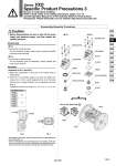
VXD23 A VXD24 B VXD25 C VXD26 D VXD27 E VXD28 F VXD29 G 0.5 0.7 Proper tightening torque N・m Metal body ( AL C37 Resin body SUS) 4 3 2 1 Flange No gaps Body Body Mounting screw Coil assembly O-ring A O-ring B Adapter Push rod assembly Spring O-ring C Mounting screw Coil assembly Stopper Return spring Armature assembly Disassembly/Assembly Procedures 1. Before disassembling, be sure to shut off the power supply and pressure supply, and then release the residual pressure. 1) Loosen the mounting screws. The coil assembly, stopper, return spring, armature assembly and body can be removed. 1) Loosen the mounting screws. The coil assembly, push rod assembly, O-rings, adapter and body can be removed. Disassembly 1) Mount the components on the body in the reverse order of disassembly. 2) Push the coil assembly against the body and tighten the screws two or more rounds diagonally (Fig. 2) in the status that there are no gaps between the coil assembly and body (Fig. 1). Tighten the screws in the order of “1→2→3→4→1→2→3→4”. . After tightening the screws, make sure that there are no gaps between the coil and body (Fig. 1). . After the disassembly and assembly have been completed, make sure that no leak occurs from the seal. Additionally, when restarting the valve, make sure that the valve operates correctly after checking the safety. Assembly Fig. 1 Fig. 2 Series VXD Specific Product Precautions 3 Be sure to read before handling. Refer to front matter 41 for Safety Instructions, pages 17 to 19 and the Operation Manual for 2 Port Solenoid Valves for Fluid Control Precautions. Please download it via our website, http://www.smcworld.com Caution 149 VX2 VXK VXD VXZ VXS VXE VXP VXR VXH VXF2 VX3 VXA A
