7-p0357-0370-vch41_en 3 / 15
10秒後にBOOKのページに移動します
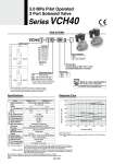
1(IN) 2(OUT) 1(IN) 2(OUT) How to Order Pressure [MPa] Note 1) DC solenoid Note 2) AC solenoid: It will cause delays around 20 to 30 msec in the OFF response time. Response time [ms] 1.0 2.0 3.0 4.0 5.0 60 50 40 30 20 10 0 Specifications Response Time Valve construction Fluid Orifice C value (Effective area) b Cv Max. operating pressure Operating pressure Fluid temperature Ambient temperature Body material Main seal material Enclosure Port size Note 1) Mounting orientation Weight Rated voltage Allowable voltage fluctuation Electrical entry Coil insulation type Power consumption Note 3) Impact/Vibration resistance Model Pilot operated, diaphragm poppet Air, Insert gas 5.0 MPa 0.5 to 5.0 MPa 5 to 80°C 5 to 80°C Brass Polyurethane elastomer Drip proof (Equivalent to IP65) G3/4, 1 (Conforming to ISO1179-1 on the pneumatic/hydraulic G thread) 300/100 m/s2 Note 2) Unrestricted 12 VDC, 24 VDC, 100 VAC, 110 VAC, 200 VAC, 220 VAC (50/60 Hz) ±10% of rated voltage DIN connector Class B 5 W (DC), 13 VA (AC) VCH41 (N.C.) VCH42 (N.O.) o17.5 22 dm3/(sbar) (110 mm2) 0.11 5.8 o16 17 dm3/(sbar) (85 mm2) 0.08 4.5 1.67 kg 1.9 kg Coil specification Valve specification Flow characteristics Made to order specifications (For details, refer to page 365) 22.0 MPa 2 Port Air Operated Valve Note 1) Impact resistance: No malfunction resulted in an impact test using a drop impact tester. The test was performed one time each in the axial and right angle directions of the main valve and armature, for both energized and de-energized states. (Value in the initial stage) Vibration resistance: No malfunction resulted in 8.3 to 2000 Hz, a one-sweep test performed in the axial and right angle directions of the main valve and armature for both energized and de-energized states. (Value in the initial stage) Note 2) Vibration resistance is 50 m/s2 when a light/surge voltage suppressor is attached. Note 3) No inrush voltages are generated in the AC solenoid because a full-wave rectifier is used. VCH42 ON response VCH41 ON response VCH41 OFF response VCH42 OFF response VCH4 1 06 Valve type 1 D G Voltage 1 2 3 4 5 6 100 VAC 200 VAC 110 VAC 220 VAC 24 VDC 12 VDC Electrical entry D DL DO DIN connector DIN connector with light Without DIN connector, with gasket Port size Thread type (Conforming to ISO1179-1 on the pneumatic/hydraulic G thread) 06 10 3/4 1 CE-compliant Nil Q . CE-compliant N.O. N.C. 2 1 . Consult with SMC for other voltages. . A surge voltage suppressor is integrated inside the coil as a standard feature. . In the symbol Port 1 and Port 2 are shown in a blocked condition, but it is not possible to use the valve in cases of reverse pressure, where the Port 2 pressure is higher than the Port 1 pressure. 5.0 MPa Pilot Operated 2 Port Solenoid Valve Series VCH40 [Option] Made to Order 358