107-120-e-lel-en 15 / 17
10秒後にBOOKのページに移動します
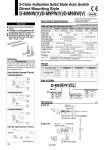
M2.5 x 4 L Indicator light 2.7 22 2.6 4 2.8 3.2 6 Most sensitive position 4 2.6 9.5 M2.5 x 4 L Indicator light Slotted set screw 2.8 4.6 4 20 2 8 3.2 6 Most sensitive position 2.7 Slotted set screw Auto Switch Specifications Weight [g] Dimensions [mm] Auto switch model 0.5 1 3 5 D-M9NW(V) 8 14 41 68 D-M9PW(V) 8 14 41 68 D-M9BW(V) 7 13 38 63 Lead wire length (m) Grommet PLC: Programmable Logic Controller D-M9NW D-M9NWV D-M9BW D-M9BWV 2-wire . 24 VDC relay, PLC . . 24 VDC (10 to 28 VDC) 2.5 to 40 mA 4 V or less 0.8 mA or less D-M9PW D-M9PWV Operating range .......... Red LED lights up. Optimum operating range .......... Green LED lights up. 3-wire IC circuit, Relay, PLC 5, 12, 24 VDC (4.5 to 28 V) 10 mA or less 40 mA or less 0.8 V or less at 10 mA (2 V or less at 40 mA) 100 μA or less at 24 VDC CE marking, RoHS In-line Perpendicular In-line Perpendicular In-line Perpendicular NPN PNP 28 VDC or less . D-M9尰W, D-M9尰WV (With indicator light) Auto switch model Electrical entry Wiring type Output type Applicable load Power supply voltage Current consumption Load voltage Load current Internal voltage drop Leakage current Indicator light Standards 𠌫Lead wires . Oilproof flexible heavy-duty vinyl cord: o2.7 x 3.2 ellipse, 0.15 mm 2, 2 cores (D-M9BW(V)), 3 cores (D-M9NW(V), D-M9PW(V)) Note) Refer to Best Pneumatics No. 2 for solid state auto switch common specifications. 傱 2-wire load current is reduced (2.5 to 40 mA). 傱 Flexibility is 1.5 times greater than the conventional model (SMC comparison). 傱 Using flexible cable as standard. 傱 The optimum operating range can be determined by the color of the light. (Red → Green ← Red) D-M9NW/M9NWV D-M9BW/M9BWV D-M9PW/M9PWV D-M9𡱖W D-M9𡱖WV 2-Color Indication Solid State Auto Switch Direct Mounting Style D-M9NW(V)/D-M9PW(V)/D-M9BW(V) How to Order Series N P B 3-wire NPN 3-wire PNP 2-wire Wiring/Output type D-M9 N W V L Nil V In-line Perpendicular Electrical entry Nil M L Z 0.5 m 1 m 3 m 5 m Lead wire length OFF ON Refer to SMC website for details about products conforming to the international standards. Precautions Caution Fix the auto switch with the existing screw installed on the auto switch body. The auto switch may be damaged if a screw other than the one supplied is used. Auto Switch Internal Circuit OUT Black DC (+) Brown DC (.) Blue Main circuit of switch DC (+) Brown OUT Black DC (.) Blue OUT (+) Brown OUT (.) Blue Main circuit of switch Main circuit of switch Indicator light/Indication method Display Red Green Red Optimum operating range Operating range RoHS 124