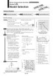
Workpiece mass [kg] Overhang: L2 [mm] 0 1 2 3 4 5 0 100 200 300 400 500 1000 mm 900 mm 800 mm 700 mm 600 mm 500 mm or less T1 a1 a2 L Speed: V [mm/s] Time [s] T2 T3 T4 Work load: W [kg] Speed: V [mm/s] 0 2 4 6 0 500 1000 LEL25L 100 W Mep m L2 Selection Procedure Selection Example ЁРWorkpiece mass: 4 [kg] ЁРSpeed: 300 [mm/s] ЁРAcceleration/Deceleration: 3,000 [mm/s2] ЁРStroke: 500 [mm] ЁРMounting position: Horizontal upward ЁРWorkpiece mounting condition: (LEL25L/Step motor) Step 1 Check the work load.speed. (Page 118) Select the target model based on the workpiece mass and speed with reference to the . Selection example) The LEL25LT-500 is temporarily selected based on the graph shown on the right side. Step 2 Check the cycle time. Calculate the cycle time using the following calculation method. Cycle time: T can be found from the following equation. T = T1 + T2 + T3 + T4 [s] T4 = 0.3 [s] T1 = V/a1 [s] T1 = V/a2 [s] T2 = [s] L . 0.5 БE V БE (T1 + T3) V ЁРT4: Settling time varies depending on the conditions such as motor types, load and in positioning of the step data. Therefore, please calculate the settling time with reference to the following value. ЁРT2: Constant speed time can be found from the following equation. ЁРT1: Acceleration time and T3: Deceleration time can be obtained by the following equation. Step 3 Check the guide moment. Based on the above calculation result, the LEL25LT-500 is selected. L : Stroke [mm] ...(Operating condition) V : Speed [mm/s] ...(Operating condition) a1: Acceleration [mm/s2] ...(Operating condition) a2: Deceleration [mm/s2] ...(Operating condition) T1: Acceleration time [s] Time until reaching the set speed T2: Constant speed time [s] Time while the actuator is operating at a constant speed T3: Deceleration time [s] Time from the beginning of the constant speed operation to stop T4: Settling time [s] Time until in position is completed Calculation example) T1 to T4 can be calculated as follows. T1 = V/a1 = 300/3000 = 0.1 [s], T3 = V/a2 = 300/3000 = 0.1 [s] T4 = 0.3 [s] Therefore, the cycle time can be obtained as follows. T = T1 + T2 + T3 + T4 = 0.1 + 1.57 + 0.1 + 0.3 = 2.07 [s] T2 = = = 1.57 [s] L . 0.5 БE V БE (T1 + T3) V 500 . 0.5 БE 300 БE (0.1 + 0.1) 300 Electric Actuator/Guide Rod Slider Step Motor (Servo/24 VDC) Series LEL Model Selection Step 1 Check the work load.speed. Step 2 Check the cycle time. Step 3 Check the allowable moment. Operating conditions 116