107-120-e-lel-en 6 / 17
10秒後にBOOKのページに移動します
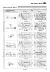
Dynamic Allowable Moment . This graph shows the amount of allowable overhang when the center of gravity of the workpiece overhangs in one direction. When the center of gravity of the workpiece overhangs in two directions, refer to the Electric Actuator Selection Software for confirmation. http://www.smcworld.com Acceleration/Deceleration 3,000 mm/s2 Wall mounting Horizontal/Ceiling mounting Orientation Load overhanging direction m: Work load [kg] L : Overhang to the work load center of gravity [mm] Model LEL25M LEL25L m L1 m L2 L3 m m L4 m L5 L6 m L6 [mm] L5 [mm] L4 [mm] L3 [mm] L2 [mm] L1 [mm] Work load [kg] Work load [kg] Work load [kg] Work load [kg] Work load [kg] Work load [kg] 800 mm stroke or less 900 mm stroke 900 mm stroke or less 1000 mm stroke 600 mm stroke or less 600 mm stroke or less 600 mm stroke or less 600 mm stroke or less 1000 mm stroke Work load [kg] L1 [mm] Work load [kg] L2 [mm] Work load [kg] L3 [mm] Work load [kg] L4 [mm] Work load [kg] L5 [mm] Work load [kg] L6 [mm] 500 mm stroke or less 700 mm stroke 800 mm stroke 600 mm stroke 500 mm stroke or less 600 mm stroke 500 mm stroke or less 600 mm stroke 500 mm stroke or less 600 mm stroke 500 mm stroke or less 600 mm stroke 1000 mm stroke 0 50 100 150 200 250 300 0 1 2 3 4 5 0 1 2 3 4 5 0 50 100 150 200 250 300 0 1 2 3 4 5 50 100 150 200 250 300 0 1 2 3 4 5 0 1 2 3 4 5 0 50 100 150 200 250 300 0 1 2 3 4 5 0 100 200 300 400 500 0 100 200 300 400 500 0 50 100 150 200 250 300 0 1 2 3 4 5 0 1 2 3 4 5 50 100 150 200 250 300 0 1 2 3 4 5 0 50 100 150 200 250 300 0 1 2 3 4 5 0 1 2 3 4 5 0 50 100 150 200 250 300 0 1 2 3 4 5 0 100 200 300 400 500 100 200 300 400 500 800 mm stroke 700 mm stroke 900 mm stroke 1000 mm stroke 0 0 0 600 mm stroke 500 mm stroke or less 900 mm stroke 117 Model Selection Series LEL A