409-428-e-lecs-en 14 / 59
10秒後にBOOKのページに移動します
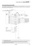
Control Signal Wiring Example: LECSA Note 1) For preventing electric shock, be sure to connect the driver circuit power supply connector (CNP1)’s protective earth (PE) terminal (marked ) to the control panel’s protective earth (PE). Note 2) For interface use, supply 24 VDC ±10% 200 mA using an external source. 200 mA is the value when all I/O command signals are used and reducing the number of inputs/outputs can decrease current capacity. Refer to “Operation Manual” for required current for interface. Note 3) The failure (ALM) is ON during normal conditions. When it is OFF (alarm occurs), stop the sequencer signal using the sequence program. Note 4) The same name signals are connected inside the driver. Note 5) For command pulse input with an open collector method. When a positioning unit loaded with a differential line driver method is used, it is 10 m or less. FX3U-𡱖𡱖MT/ES (Manufactured by Mitsubishi Electric) PLC CNP1 Sequencer power supply PE S/S 24V 0V L . N YS0/0S0 COM1 Y010 COM3 COM2 X𡱖𡱖𡱖 X𡱖𡱖𡱖 X𡱖𡱖𡱖 Y004 LECSA 24 VDC CN1 DICOM OPC DOCOM PP NP CR RD LG SD INP OP Note 4) Note 4) Note 2) CN1 CN1 10 m or less 2 m or less Note 5) 10 m or less Note 1) 1 2 13 23 25 5 11 14 Plate 10 21 9 12 15 Plate 20 ALM Forced stop EM1 Servo ON Reset Forward rotation stroke end Reverse rotation stroke end 8 SON 4 RES 3 LSP 6 LSN 7 MBR LA 16 LAR 17 LB 18 LBR 19 LZ SD LZR 14 LG Failure Note 3) Electromagnetic brake interlock A-phase pulse encoder (Differential line driver) B-phase pulse encoder (Differential line driver) Z-phase pulse encoder (Differential line driver) Control common RA1 RA2 This wiring example shows connection with a PLC (FX3U-𡱖𡱖MT/ES) manufactured by Mitsubishi Electric as when used in position control mode. Refer to the LECSA operation manual and any technical literature or operation manuals for your PLC and positioning unit before connecting to another PLC or positioning unit. Note 4) 431 AC Servo Motor Driver Series LECS𡱖