409-428-e-lecs-en 17 / 59
10秒後にBOOKのページに移動します
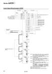
Note 1) For preventing electric shock, be sure to connect the driver’s protective earth (PE) terminal (marked ) to the control panel’s protective earth (PE). Note 2) For interface use, supply 24 VDC ±10% 150 mA using an external source. Note 3) The failure (ALM) is ON during normal conditions. When it is OFF (alarm occurs), stop the sequencer signal using the sequence program. Note 4) The same name signals are connected inside the driver. Note 5) Use the following SSCNET 3 optical cables. Refer to “SSCNET 3 optical cable” on page 435 for cable models. Note 6) Connections from Axis 2 onward are omitted. Note 7) Up to 16 axes can be set. Note 8) Be sure to place a cap on unused CN1A/CN1B. PE LECSS LECSS CN3 Note 4) CN3 10 m or less 10 m or less Note 4) Note 1) Note 6) Note 7) Note 7) Note 6) Note 7) Note 6) Note 7) 13 9 4 11 DICOM MBR Forced stop Upper stroke limit (FLS) Lower stroke limit (RLS) Proximity dog (DOG) 5 D0COM 3 EM1 20 D11 2 D12 12 D13 19 INP 15 ALM 10 DICOM 6 LA 16 LAR 7 LB 17 LBR 8 LZ MO1 1 LG 14 MO2 Plate SD LG 18 LZR Electromagnetic brake interlock Note 2) In position Failure Note 3) A-phase pulse encoder (Differential line driver) SSCNET 3 optical cable Note 5) (Option) SSCNET 3 optical cable Note 5) (Option) Cap Note 8) Servo system controller B-phase pulse encoder (Differential line driver) Z-phase pulse encoder (Differential line driver) Control common Analog monitor 1 Analog monitor 2 SW1 SW2 (Axis 2) 1 2 SW1 SW2 1 2 RA2 RA3 2 m or less Control Signal Wiring Example: LECSS CN1A CN1B CN1A CN1B CN1A CN1B CN1A CN1B RA1 Cable Cable model Cable length SSCNET 3 optical cable LE-CSS- 0.15 m to 3 m LECSS (Axis 3) SW1 SW2 1 2 LECSS (Axis n) SW1 SW2 1 2 24 VDC Note 2) 434 Series LECS