409-428-e-lecs-enü@ü@ü@48 / 59
10ĢbīŃé╔BOOKé╠āyü[āWé╔ł┌ō«éĄé▄éĘ
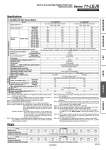
Specifications 11-LEJS40, 63 AC Servo Motor Weight Model 11-LEJS40T6 11-LEJS63T7 Actuator specifications Stroke [mm] Note 1) 200, 300, 400, 500, 600, 700, 800 900, 1000, 1200 300, 400, 500, 600, 700, 800, 900 1000, 1200, 1500 Work load [kg] Note 2) Horizontal 30 55 45 85 Vertical 5 10 10 20 Speed Note 3) [mm/s] Stroke range Up to 500 1200 600 1200 600 501 to 600 1050 520 1200 600 601 to 700 780 390 1200 600 701 to 800 600 300 930 460 801 to 900 480 240 740 370 901 to 1000 390 190 600 300 1001 to 1100 320 160 500 250 1101 to 1200 270 130 420 210 1201 to 1300 . . 360 180 1301 to 1400 . . 310 150 1401 to 1500 . . 270 130 Max. acceleration/deceleration [mm/s2] 20,000 (For limit according to work load and duty ratio, refer to ügWork Load.Acceleration/ Deceleration Graphüh on pages 15 and 16 in the WEB catalog of the electric actuator LEJ series.) Positioning repeatability [mm] Note 4) Basic type ü}0.02 High precision type ü}0.01 Lost motion [mm] Note 5) Basic type 0.1 or less High precision type 0.05 or less Lead [mm] 16 8 20 10 Impact/Vibration resistance [m/s2] Note 6) 50/20 Actuation type Ball screw Guide type Linear guide Grease Ball screw/Linear guide portion Low particle generation grease Cleanliness class Note 7) ISO Class 4 (ISO14644-1) Allowable external force [N] 20 Operating temperature range [üŗC] 5 to 40 Operating humidity range [%RH] 90 or less (No condensation) Regeneration option May be required depending on speed and work load. Refer to page 56-1 in the WEB catalog of the electric actuator LEJ series. Electric specifications Motor output [W]/Size [mm] 100/«40 200/«60 Motor type AC servo motor (200 V) Encoder Absolute 22-bit encoder (Resolution: 4,194,304 p/rev) Power consumption [W] Note 8) Horizontal 65 80 Vertical 165 235 Standby power consumption when operating [W] Note 9) Horizontal 2 2 Vertical 10 12 Max. instantaneous power consumption [W] Note 10) 445 725 Lock unit specifications Type Note 11) Non-magnetizing lock Holding force [N] 101 203 330 660 Power consumption [W] at 20üŗC Note 12) 6.3 7.9 Rated voltage [V] 24 VDC 0 .10% Model 11-LEJS40 Stroke [mm] 200 300 400 500 600 700 800 900 1000 1200 Product weight [kg] 5.6 6.4 7.1 7.9 8.7 9.4 10.2 11.0 11.7 13.3 Additional weight with lock [kg] 0.2 (Incremental encoder)/0.3 (Absolute encoder) Model 11-LEJS63 Stroke [mm] 300 400 500 600 700 800 900 1000 1200 1500 Product weight [kg] 11.4 12.7 13.9 15.2 16.4 17.7 18.9 20.1 22.6 26.4 Additional weight with lock [kg] 0.4 (Incremental encoder)/0.7 (Absolute encoder) 20-2 Electric Actuator/High Rigidity Slider Type Ball Screw Drive Series 11-LEJS Clean Room Specification Note 1) Please consult with SMC for non-standard strokes as they are produced as special orders. Note 2) For details, refer to ügSpeed.Work Load Graph (Guide)üh on page 12 in the WEB catalog of the electric actuator LEJ series. Note 3) The allowable speed changes according to the stroke. Note 4) Conforming to JIS B 6191-1999 Note 5) A reference value for correcting an error in reciprocal operation. Note 6) Impact resistance: No malfunction occurred when the actuator was tested with a drop tester in both an axial direction and a perpendicular direction to the lead screw. (Test was performed with the actuator in the initial state.) Vibration resistance: No malfunction occurred in a test ranging between 45 to 2000 Hz. Test was performed in both an axial direction and a perpendicular direction to the lead screw. (Test was performed with the actuator in the initial state.) Note 7) The amount of particle generation changes according to the operating conditions and suction flow rate. Refer to the particle generation characteristics for details. Note 8) The power consumption (including the driver) is for when the actuator is operating. Note 9) The standby power consumption when operating (including the driver) is for when the actuator is stopped in the set position during the operation. Note 10) The maximum instantaneous power consumption (including the driver) is for when the actuator is operating. This value can be used for the selection of the power supply. Note 11) Only when motor option ügWith locküh is selected. Note 12) For an actuator with lock, add the power consumption for the lock. Note 13) Sensor magnet position is located in the table center. For detailed dimensions, refer to ügAuto Switch Mounting Positionüh on page 38-1 in the WEB catalog of the electric actuator LEJ series. Note 14) Do not allow collisions at either end of the table traveling distance. Additionally, when running the positioning operation, do not set within 2 mm of both ends. Note 15) For ügManufacture of Intermediate Strokesüh, please contact SMC. (LEJS40/Manufacturable stroke range: 200 to 1200 mm, LEJS63/ Manufacturable stroke range: 300 to 1500 mm) LECSS-T 11-LEJS LEYG LEY LEJS/LEJB LEFS/LEFB A