8-p1242-1258-yuatucylinder_en 6 / 18
10秒後にBOOKのページに移動します
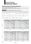
Hydraulic Cylinders Technical Data 2 Stroke Selection (maximum stroke based on buckling strength) Refer to the stroke range limit charts regarding rod buckling due to load mass. The values in these tables indicate the maximum stroke that can be used in a situation when air is being supplied while the cylinder is stopped in an intermediate position by an external force acting on the piston rod and/or by an external stopper. Since the maximum usable stroke varies depending on the diameter of the piston rod and operating conditions, verify the applicability using the stroke range limit charts. Series CHM Stroke range limit charts: Bore sizes o20, o25, o32, o40 Symbol q r u t u e t y i e Mounting orientation Symbol Mounting orientation Symbol Mounting orientation Symbol Mounting orientation Bore size o20 Bore size o25 Load (kN) Load (kN) Stroke (mm) 1000 500 100 50 0.05 0.1 0.5 1 2 0.05 0.1 0.5 1 2 F F F F F F F F F F Load (kN) Load (kN) Bore size o32 Bore size o40 Stroke (mm) 1000 500 100 50 0.05 0.1 0.5 1 2 3 0.05 0.1 0.5 1 2 5 q r e t y i u q y t r i e u q e r t y i u q r e t y i u 1246