ex-pcw 10 / 41
10秒後にBOOKのページに移動します
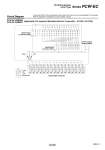
Circuit Diagram PCW-EC16ZBM00 PCW-EC16ZBM01 [Applicable PLC example: Mitsubishi Electric Corporation A1SX41, A1SY42] Consult with SMC for the manufacturers and models other than shown as the applicable PLC examples. Refer to page 603-1 for details such as pin number or layout. Input/output connector Input/output connector (CS0) Power supply terminal block Input/output connector (CS1) CNF 4 3 2 1 CNE 4 3 2 1 CND 4 3 2 1 CNC 4 3 2 1 CNB 4 3 2 1 CNA 4 3 2 1 CN9 4 3 2 1 CN8 4 3 2 1 CN7 4 3 2 1 CN6 4 3 2 1 CN5 4 3 2 1 CN4 4 3 2 1 CN3 4 3 2 1 CN2 4 3 2 1 CN1 4 3 2 1 4 3 2 1 CN0 S1 *S2 4 3 2 1 INPUT/OUTPUT 0 VDC (S2) 24 VDC 9 11 13 15 17 19 21 23 25 27 29 31 33 35 37 39 2 4 6 8 10 12 14 16 18 20 22 24 26 28 30 32 34 36 38 40 1 3 5 7 1 3 5 7 9 11 13 15 17 19 2 4 6 8 10 12 14 16 18 20 F E D C B A 9 8 7 6 5 4 3 2 1 0 0 1 2 3 4 5 6 7 8 9 A B C D E F Green Red 589-2 Series PCW-EC PC Wiring System e-con Type A