ex-pcw 39 / 41
10秒後にBOOKのページに移動します
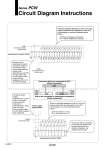
Power supply terminal block 2 1 3 4 5 6 7 8 9 10 11 12 13 14 15 16 17 18 19 20 2F 27 26 2E 25 2D 24 2C 23 2B 22 2A 21 29 20 28 Input/output connector (CN2) CS1 CS2 CS0 To CS0 (Connected to PLC) 9 11 13 15 17 19 21 23 25 27 29 31 33 35 37 39 2 4 6 8 10 12 14 16 18 20 22 24 26 28 30 32 34 36 38 40 1 3 5 7 1F 1E 1D 1C 1B 1A 19 18 17 16 15 14 13 12 11 10 2F 2E 2D 2C 2B 2A 29 28 27 26 25 24 23 22 21 20 These are indicating addresses on the PLC I/O card. However indications vary dependant on each PLC, in this catalog, our common indications are as follows: 15 6th point address out of 32 point 1F 16th point address out of 32 point Input/output connector (CS0) To CS1 (Connected to sensor, solenoid valve) To CS2 (Connected to sensor, solenoid valve) Side to be connected to input/output equipment (20-pin connector) Power supply terminal block Connector side to be connected to PLC (40-pin connector) Power supply terminal block These are indicating addresses on the PLC I/O card However indications vary dependant on each PLC, in this catalog, our common indications are as follows: 25 22nd address out of 32 2F 16th address out of 32 603-1 Series PCW Circuit Diagram Instructions Numbers on the input/output connector indicate pin number of the connector itself. As pin assignment (pin layout) varies depending on each PLC I/O card, refer to the Circuit Diagram of this product and pin assignment of PLC I/O card when selecting. To wire the power supply: Connect 24V to (+) and 24G to (-) using the power cable and connector, or alternatively wire using your own cable. This connection offers 24 VDC power supply to each equipment. You can use this by connecting to the PCW unit together with the input/output unit, or by directly connecting to the manifold solenoid valve. A