es11-109-s0700 20 / 32
10秒後にBOOKのページに移動します
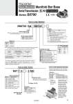
0 1 8 9 6 7 14 15 D side U side 3 2 1 Stations …… ……… ……… ……… Symbol Manifold pitch 8.5 Nil Rc F G N NPT T NPTF Type of actuation Single Double, Dual 3-port Number of solenoids 1 2 Standard station Max. number of stations for special wiring specifications Max. number of solenoids 1 to 8 stations 16 stations 16 Symbol Stations 02 2 stations … … 16 16 stations Nil Positive common N Negative common Symbol Type Nil Standard R External pilot Note) Symbol Specifications 1 2-position single 2 2-position double 3 3-position closed center A 4-position dual 3-port (N.C. + N.C.) [Exhaust center] B 4-position dual 3-port (N.O. + N.O.) [Pressure center] C 4-position dual 3-port (N.C. + N.O.) Symbol Port size M5 M5 thread Metric C2 With o2 One-touch fitting C3 With o3.2 One-touch fitting C4 With o4 One-touch fitting CM Mixed sizes and with port plug Note) N1 With o1/8" One-touch fitting N3 With o5/32" One-touch fitting Inch NM Mixed sizes and with port plug Note) How to Order Manifold How to Order Valves Symbol Type Nil None K Note 2) Special wiring specifications (Except double wiring) R Note 3) External pilot SS0755 08 C4 S Kit EX510 serial wiring SI Unit output polarity Cylinder port size Option Note) Specify “Mixed sizes and with port plug” on the manifold specification sheet. Note 1) When multiple options are specified, indicate them alphabetically. Example) -KR Note 2) Indicate the wiring specifications for mixed single and double wirings. Note 3) For details, refer to page 20. . For manifold optional parts, refer to pages 20 to 22. SA Voltage: 24 VDC M-type plug connector, without lead wire (With light/surge voltage suppressor) Electrical entry Type of actuation S07 1 5 5 MO Base Mounted Manifold Function 1 set.Manifold base part no. 3 sets.Valve part no. (Stations 1 to 3) 3 sets.Valve part no. (Stations 4 to 6) 2 sets.Valve part no. (Stations 7 to 8) How to Order Manifold Assembly Specify the part numbers for valves and options together beneath the manifold base part number.