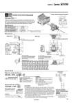
To cylinder port SUP side pressure (P1) Cylinder side pressure (P2) 2n x C4 C4: o4 One-touch fitting assembly 21.5 (5) 10.5 1.7 67 . 4.5 33 Residual pressure release manual override Mounting hole for M2.5 Mounting hole for M3 (22.5) 0.5 (17.5) 11 8 46.5 (43) 2.5 38 29.5 2n x C3, C4, M5 C3: o3.2 One-touch fitting assembly C4: o4 One-touch fitting assembly M5: M5 thread 21.5 (5) 10.5 (14) 38 (30) (3.5) 3 29 2n x C4 C4: o4 One-touch fitting assembly 18 P=11 15.5 L1 L2 L3 32.2 5.5 1.7 67 . 4.5 D side Stations 1 2 3 n U side Residual pressure release manual override 2n x C3, C4, M5 C3: o3.2 One-touch fitting assembly C4: o4 One-touch fitting assembly M5: M5 thread 7.5 18 29 45.5 2.5 DIN rail clamping screw 2-position 1(P) 3(R2) 5(R1) 2(B) 4(A) 1(P) 5(R1) 3(R2) Part no. Tightening torque VQ1000- FPG-FB 0.22 to 0.25 N・m Nil None D DIN rail mounting (For manifold) F With bracket N With name plate 01 1 station … … 16 16 stations M5 M5 thread C3 o3.2 One-touch fitting C4 o4 One-touch fitting C4 o4 One-touch fitting Max. operating pressure 0.8 MPa Min. operating pressure 0.15 MPa Ambient and fluid temperature .5 to 50°C Flow-rate characteristics: C 0.60 dm3/(s・bar) Max. operating frequency 180 c.p.m VQ1000 FPG L n 11 12 13 14 15 16 17 18 19 20 L1 141 152 163 174 185 196 207 218 229 240 L2 162.5 175 187.5 187.5 200 212.5 225 237.5 250 250 L3 173 185.5 198 198 210.5 223 235.5 248 260.5 260.5 L n 1 2 3 4 5 6 7 8 9 10 L1 31 42 53 64 75 86 97 108 119 130 L2 50 62.5 75 87.5 100 112.5 125 125 137.5 150 L3 60.5 73 85.5 98 110.5 123 135.5 135.5 148 160.5 Note) Based on JIS B 8375-1981 (Supply pressure: 0.5 MPa) Specifications Dimensions Single Unit Manifold Dimensions Formula L1 = 11n + 20 n: Station (Maximum 20 stations) How to Order Single unit, double check block OUT side port size Option IN side port size Bracket Assembly VVQ1000 FPG Stations VVQ1000-FPG-06…6-station manifold . VQ1000-FPG-C4M5-D: 6 sets Double check block Manifold (DIN rail mounting) Caution It is used on the outlet side piping to keep the cylinder in the intermediate position for long periods of time. Combining the double check block with a built-in pilot type double check valve and a 2-position single/double solenoid valve will permit this block to be used for preventing the dropping at the cylinder stroke end when the SUP residual pressure is released. C4 06 M5 F . Air leakage from the pipe between the valve and cylinder or from the fittings will prevent the cylinder from stopping for long periods of time. Check for the leakage using neutral household detergent, such as dish washing soap. Also, check the cylinder’s tube gasket, piston seal and rod seal for air leakage. . Since One-touch fittings allow slight air leakage, screw piping (with M5 thread) is recommended when stopping the cylinder in the middle for long periods of time. . M5 fitting assembly is attached, not incorporated into the double check block. After screwing in the M5 fittings, mount the assembly on the double check block. {Tightening torque: 0.8 to 1.2 N・m} . If the exhaust of the double check block is restricted too much, the cylinder may not operate properly and may not stop intermediately. Double check block (Separated) VQ1000-FPG-mm When ordering a double check block, order the DIN rail mounting [-D]. Note) When multiple symbols are specified, indicate them alphabetically. Example) -DN Note) This torque is used to mount the bracket on the double check block. Body Ported Base Mounted 22 Options Series S0700