es20-226-cj2 104 / 120
10秒後にBOOKのページに移動します
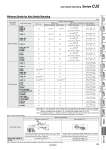
B A Auto switch model With 2 auto switches Different surfaces Note 1) Same surface Note 1) The proper auto switch mounting position is 5.5 mm inward from the switch holder edge. The above A and B indicate values for band mounting in the table of page 99. The auto switch is mounted by slightly displacing it in a direction (cylinder tube circumferential exterior) so that the auto switch and lead wire do not interfere with each other. D-M9𡱖/M9𡱖W/M9𡱖A Less than 20 stroke Note 2) Less than 55 stroke Note 2) D-A9𡱖 . Less than 50 stroke Note 2) Note 3) When “n” is an odd number, an even number that is one larger than this odd number is used for the calculation. Note 4) When “n” is an odd number, an even number that is one larger than this odd number is used for the calculation. However, the minimum even number is 4. So, 4 is used for the calculation when “n” is 1 to 3. Note 5) The dimension stated in ( ) shows the minimum mountable stroke when the auto switch does not project from the end face of the cylinder body and the lead wire bending space is not hindered. Note 1) Auto switch mounting Note 2) Minimum stroke for auto switch mounting in styles other than those mentioned in Note 1. Auto switch D-M9𡱖(V) D-M9𡱖W(V) D-M9𡱖A(V) (mm) Auto switch mounting Auto switch model Number of auto switches With 1 pc. With 2 pcs. With n pcs. (n: Number of auto switches) Different surfaces Same surface Different surfaces Same surface Band mounting D-M9l D-M9lW D-M9lA D-A9l 10 15 Note 1) 45 Note 1) 15 + 35(n . 2) 2 (n = 2, 4, 6…) Note 3) 45 + 15 (n . 2) (n = 2, 3, 4, 5…) D-M9lV 5 15 Note 1) 35 15 + 35(n . 2) 2 (n = 2, 4, 6…) Note 3) 35 + 25 (n . 2) (n = 2, 3, 4, 5…) D-M9lWV D-M9lAV 10 15 Note 1) 35 15 + 35(n . 2) 2 (n = 2, 4, 6…) Note 3) 35 + 25 (n . 2) (n = 2, 3, 4, 5…) D-A9lV 5 10 35 10 + 35(n . 2) 2 (n = 2, 4, 6…) Note 3) 35 + 25 (n . 2) (n = 2, 3, 4, 5…) D-H7l/H7lW D-H7BA D-H7NF 10 15 60 15 + 45(n . 2) 2 (n = 2, 4, 6…) Note 3) 60 + 22.5 (n . 2) (n = 2, 3, 4, 5…) D-C7l D-C80 10 15 50 15 + 40(n . 2) 2 (n = 2, 4, 6…) Note 3) 50 + 20 (n . 2) (n = 2, 3, 4, 5…) D-H7C D-C73C D-C80C 10 15 65 15 + 50(n . 2) 2 (n = 2, 4, 6…) Note 3) 50 + 27.5 (n . 2) (n = 2, 3, 4, 5…) Rail mounting D-M9lV 5 . 5 . 10 + 10 (n . 2) (n = 4, 6…) Note 4) D-A9lV 5 . 10 . 10 + 15 (n . 2) (n = 4, 6…) Note 4) D-M9l D-A9l 10 (5) Note 5) . 10 . 15 + 15 (n . 2) (n = 4, 6…) Note 4) D-M9lWV D-M9lAV 10 . 15 . 15 + 15 (n . 2) (n = 4, 6…) Note 4) D-M9lW 15 (10) Note 5) . 15 . 20 + 15 (n . 2) (n = 4, 6…) Note 4) D-M9lA 15 (10) Note 5) . 20 (15) Note 5) . 20 + 15 (n . 2) (n = 4, 6…) Note 4) D-F7l D-J79 5 . 5 . 15 + 15 (n . 2) (n = 4, 6…) Note 4) D-F7lV D-J79C 5 . 5 . 10 + 10 (n . 2) (n = 4, 6…) Note 4) D-F7lW/J79W D-F7BA/F79F/F7NT 10 . 15 . 15 + 20 (n . 2) (n = 4, 6…) Note 4) D-F7lWV D-F7BAV 10 . 15 . 10 + 15 (n . 2) (n = 4, 6…) Note 4) D-A7l/A80 D-A7lH/A80H D-A73C/A80C 5 . 10 . 15 + 10 (n . 2) (n = 4, 6…) Note 4) D-A7lH D-A80H 5 . 10 . 15 + 15 (n . 2) (n = 4, 6…) Note 4) D-A79W 10 . 15 . 10 + 15 (n . 2) (n = 4, 6…) Note 4) Minimum Stroke for Auto Switch Mounting 102 Auto Switch Mounting Series CJ2 CBJ2 CJ2RK CJ2RK CJ2R CJ2R CJ2ZW CJ2Z CJ2K CJ2K CJ2 CJ2W CJ2 With End Lock Direct Mount, Non-rotating Rod Direct Mount Built-in Speed Controller Non-rotating Rod Standard Single Acting, Spring Return/Extend Double Acting, Single Rod Single Acting, Spring Return/Extend Double Acting, Single Rod Double Acting, Double Rod Double Acting, Single Rod Single Acting, Spring Return/Extend Double Acting, Single Rod Single Acting, Spring Return/Extend Double Acting, Double Rod Double Acting, Single Rod Made to Order Auto Switch