es20-226-cj2 65 / 120
10秒後にBOOKのページに移動します
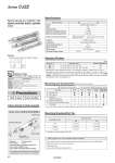
Auto switch Band mounting Double clevis Pivot bracket Double knuckle joint Symbol Double acting, Single rod, Rubber bumper Cylinder model: CDJ2ZD16-60Z-NW-M9BW-B Mounting D: Double clevis Pivot bracket N: Yes Rod end bracket W: Double knuckle joint Auto switch D-M9BW: 2 pcs. Auto switch mounting B: Band mounting * Pivot bracket, double knuckle joint and auto switch are shipped together with the product, but not assembled. Ordering Example of Cylinder Assembly Space-saving air cylinder with speed controller built-in cylinder cover Made to Order (For details, refer to pages 107 to 116.) Symbol Specifications -XAl Change of rod end shape -XC51 With hose nipple -XC85 Grease for food processing equipment -X446 PTFE grease Refer to page 117 before handling. Precautions Bore size (mm) 10 16 Action Double acting, Single rod Fluid Air Proof pressure 1 MPa Maximum operating pressure 0.7 MPa Minimum operating pressure 0.06 MPa Ambient and fluid temperature Without auto switch : .10°C to 70°C (No freezing) With auto switch : .10°C to 60°C Cushion Rubber bumper Lubrication Not required (Non-lube) Stroke length tolerance +1.0 0 Speed controller Built-in Piston speed 50 to 750 mm/s Allowable kinetic energy 0.035 J 0.090 J Specifications * Manufacture of intermediate strokes at 1 mm intervals is possible. (Spacers are not used.) * Applicable strokes should be confirmed according to the usage. For details, refer to “Air Cylinders Model Selection” on front matter pages of the Best Pneumatics No. 2 or the WEB catalog. In addition, the products that exceed the standard stroke might not be able to fulfill the specifications due to the deflection etc. Bore size Standard stroke Maximum manufacturable stroke 10 15, 30, 45, 60, 75, 100, 125, 150 400 16 15, 30, 45, 60, 75, 100, 125, 150, 175, 200 400 (mm) Standard Strokes V…Mounted on the product. v…Can be ordered within the cylinder model. * A pin and retaining rings are shipped together with double clevis and double knuckle joint. Mounting Basic Foot Flange Double* clevis Double clevis (including T-bracket) Standard Mounting nut V V V . . Rod end nut V V V V V Clevis pin . . . V V Option Single knuckle joint v v v v v Double knuckle joint* v v v v v Rod end cap (Flat/Round type) v v v v v T-bracket . . . v V Mounting and Accessories/For details, refer to page 20. * T-bracket is used with double clevis (D). Mounting bracket Bore size (mm) 10 16 Foot CJ-L010C CJ-L016C Flange CJ-F010C CJ-F016C T-bracket* CJ-T010C CJ-T016C Mounting Brackets/Part No. Refer to pages 97 to 104 for cylinders with auto switches. . Auto switch proper mounting position (detection at stroke end) and its mounting height . Minimum stroke for auto switch mounting . Operating range . Auto switch mounting brackets/Part no. 63 Series CJ2Z